
Operator's Manual
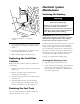

1. With a buc k et on the loader ar ms , lo w er the
buc k et to the g round so that the front of the
traction unit lifts off of the g round a few
inc hes .
2. Stop the engine , and remo v e the k ey .
3. Using a w ater hose or pressure w asher , remo v e
dir t from eac h trac k system.
Important: Ensur e that y ou use
high-pr essur e w ater to w ash onl y the track
ar ea. Do not use a high-pr essur e w asher to
clean the r est of the traction unit. Do not use
high pr essur e w ater betw een the dri v e spr ock et
and the traction unit or y ou may dama ge
the motor seals. High-pr essur e w ashing can
dama ge the electrical system and h y draulic
v alv es or deplete g r ease.
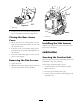
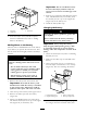
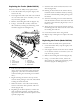
Important: Ensur e that y ou full y clean the
r oad wheels, the tension wheel, and the dri v e
spr ock et ( Figur e 43 ). T he r oad wheels should
r otate fr eel y when clean.
Figure 43
1. Track 3. Road wheels
2. Drive sprocket 4. Tension wheel
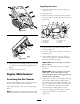
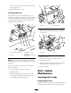
Adjusting the Track Tension
Chec k and adjust the trac k tension after the first
50 operating hours and ev er y 100 operating hours
thereafter . T here should be 2-3/4 inc hes (7 cm)
betw een the tension n ut and the bac k of the
tension tube ( Figure 44 ). If not, adjust the trac k
tension using the follo wing procedure:
Figure 44
1. 2-3/4 inches (7 cm)
1. Lo w er the loader ar ms , stop the engine , and
remo v e the k ey .
2. Lift/suppor t the side of the unit to be w ork ed
on so that the trac k is off of the g round.
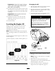
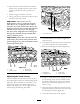
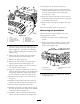
3. R emo v e the loc king bolt and n ut ( Figure 45 ).
Figure 45
1. Locking bolt 3. Tension tube
2. Tensioning screw
4. Tension wheel
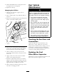
4. Using a 1/2 inc h dri v e soc k et ( Figure 46 ), tur n
the tensioning screw counter -cloc kwise until
the distance betw een the tension n ut and the
bac k of the tension tube ( Figure 44 ) is 2-3/4
inc hes (7 cm).
5. Align the closest notc h in the tension screw to
the loc king bolt hole and secure the screw with
the loc king bolt and n ut ( Figure 45 ).
6. Lo w er the traction unit to the g round.
38