
Operator's Manual

Controls
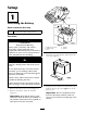
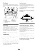
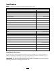
Become familiar with all the controls ( Figure 9 )
before y ou star t the engine and operate the traction
unit.
Figure 9
1. Auxiliary hydraulics lever 7. Loader arm/attachment tilt
lever
2. Key switch 8. Parking brake lever
3. Hour meter
9. Reference bar
4. Fuel gauge 10. Traction control
5. Indicator lights and glow
plug switch
11. Loader valve lock
6. Throttle lever
Key Switch
T he k ey switc h, used to star t and stop the engine ,
has three positions: off , r un, and star t.
T o star t the engine , rotate the k ey to the star t
position. R elease the k ey when engine star ts and it
will mo v e automatically to the r un position.
T o stop the engine , rotate the k ey to the off
position.
Throttle Lever
Mo v e the control forw ard to increase the engine
speed and rearw ard to decrease speed.
Reference Bar
W hen dri ving the traction unit, use the reference
bar as a handle and a lev erag e point for controlling
the traction control and the auxiliar y h y draulics
lev er . T o ensure smooth, controlled operation, do
not tak e both hands off of the reference bar while
operating the traction unit.
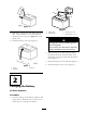
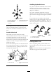
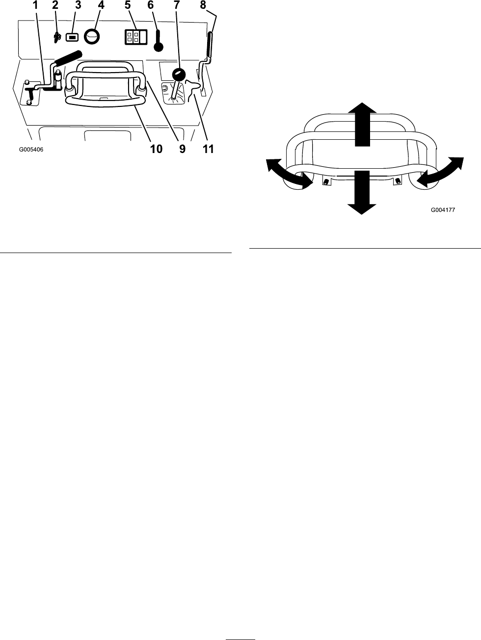
Traction Control
T o mo v e forw ard, mo v e the traction control
forw ard. T o mo v e rearw ard, mo v e the traction
control rearw ard ( Figure 10 ).
T o tur n, rotate the traction control in the desired
direction ( Figure 10 ).
T he far ther y ou mo v e the traction control in any
direction, the faster the traction unit will mo v e in
that direction.
T o stop , release the traction control.
Figure 10
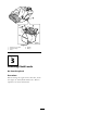
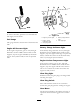
Loader Arm/Attachment Tilt Lever
T o tilt the attac hment forw ard, slo wly mo v e the
lev er to the right ( Figure 11 ).
T o tilt the attac hment rearw ard, slo wly mo v e the
lev er to the left ( Figure 11 ).
T o lo w er the loader ar ms , slo wly mo v e the lev er
forw ard ( Figure 11 ).
T o raise the loader ar ms , slo wly mo v e the lev er
rearw ard ( Figure 11 ).
Y ou can also push the lev er fully forw ard into a
detent position ( Figure 11 ) to release the loader
ar ms so that the attac hment rests on the g round.
T his allo ws attac hments suc h as the lev eler and
the h y draulic blade to follo w the contours of the
g round (i.e ., float) when g rading .
16