
Operator's Manual

Stability Data
T he follo wing tables list the maxim um slope recommended for the traction unit in the positions listed in
the tables . Slopes o v er the listed deg ree ma y cause the traction unit to become unstable . T he data in the
tables assume that the loader ar ms are fully lo w ered; raised ar ms ma y affect the stability .
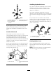
In eac h attac hment man ual is a set of three stability ratings , one for eac h hill position. T o deter mine the
maxim um slope y ou can tra v erse with the attac hment installed, find the deg ree of slope that cor responds
to the stability ratings of the attac hment. Example: If the attac hment installed on a TX model 22319
traction unit has a F ront Uphill rating of B , a R ear Uphill rating of D , and a Side Uphill rating of C ,
then y ou could dri v e forw ard up a 19° slope , rearw ard up a 12° slope , or sidew a ys on a 14° slope , as
listed in the follo wing table .
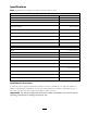
Model 22333
Maximum Recommended Slope when
Operating with:
Front Uphill Rear Uphill Side Uphill
Conguration
Traction unit without attachment
11° 21° 19°
Traction unit with an attachment rated with one of the following
stability ratings for each slope position:*
A
25° 25° 20°
B
19° 19° 18°
C
16° 15° 14°
D
10° 12° 9°
E
5° 5° 5°
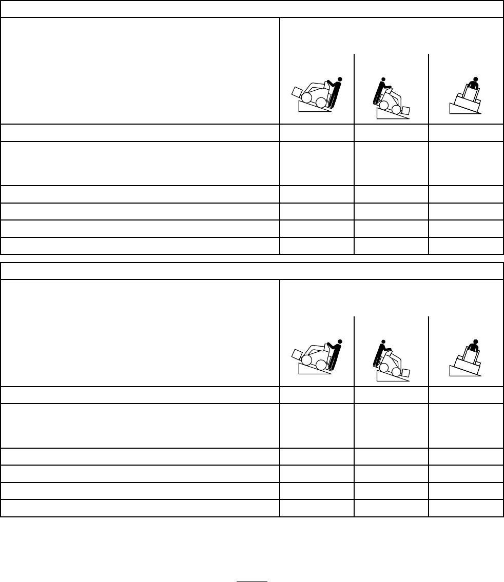
Model 22334
Maximum Recommended Slope when
Operating with:
Front Uphill Rear Uphill Side Uphill
Conguration
Traction unit without attachment
12° 19° 21°
Traction unit with an attachment rated with one of the following
stability ratings for each slope position:*
A
25° 25° 23°
B
22° 22° 20°
C
18° 16° 14°
D
10° 10° 10°
E
5° 5° 5°
20