
Operator's Manual
disconnect the c harg er leads from the batter y
posts ( Figure 39 ).
5. R e place the batter y co v er .
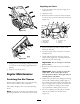
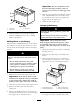
Servicing the Fuses
T he electrical system is protected b y fuses . It
requires no maintenance; ho w ev er , if a fuse blo ws ,
c hec k the component/circuit for a malfunction or
a shor t. Figure 40 illustrates the fuse bloc k and
identifies the fuse positions .
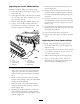
Figure 40
1. 30 amp. fuse—main circuit 3. 10 amp fuse—control
panel/relay
2. Empty
4. Open position for optional
accessories
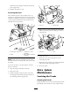
Note: If the traction unit will not star t, either
the main circuit or control panel/rela y fuse could
be blo wn.
T o access the fuses , y ou m ust remo v e the fuse
panel, as follo ws:
1. Stop the engine and remo v e the k ey .
2. Raise the hood.
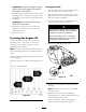
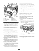
3. Pull the hair pin cotter from the end of the
hood prop-rod and slide the prop rod out of
the retaining brac k ets ( Figure 41 ).
Figure 41
1. Prop-rod
2. Hairpin cotter
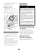
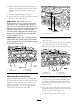
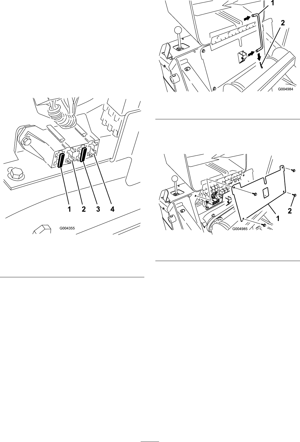
4. R emo v e the 4 screws securing the fuse panel
and then pull the panel out and up to remo v e
it ( Figure 42 ).
Figure 42
1. Fuse panel
2. Screw
5. Chec k the fuses .
6. Install the fuse panel using the 4 screws
remo v ed previously .
7. Install the prop-rod into the retaining brac k ets
and secure it with the hair pin cotter .
8. Close the hood.
Drive System
Maintenance
Servicing the Tracks
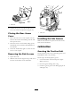
Cleaning the Tracks
Chec k the trac ks for ex cessi v e w ear and clean them
periodically . If the trac ks are w or n, re place them.
37