Form No. 3359-252 Rev B TX 525 Compact Utility Loader Model No. 22333—Serial No. 280000001 and Up Model No. 22334—Serial No. 280000001 and Up G004222 Register at www.Toro.com.
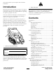
This spark ignition system complies with Canadian ICES-002. Figure 2 Introduction 1. Safety alert symbol Read this information carefully to learn how to operate and maintain your product properly and to avoid injury and product damage. You are responsible for operating the product properly and safely. This manual uses 2 other words to highlight information. Important calls attention to special mechanical information and Note emphasizes general information worthy of special attention.
Safety Removing the Side Screens ................................. 29 Installing the Side Screens................................... 29 Lubrication............................................................. 29 Greasing the Traction Unit ................................. 29 Engine Maintenance............................................... 30 Servicing the Air Cleaner .................................... 30 Servicing the Engine Oil ..................................... 30 Fuel System Maintenance ..........
• Inspect the area where the equipment is to be used and remove all objects such as rocks, toys, and wire which can be thrown by the machine. • Use extra care when handling fuels. They are flammable and vapors are explosive. – Use only an approved container – Never remove the fuel cap or add fuel with the engine running. Allow the engine to cool before refueling. Do not smoke. – Never refuel or drain the machine indoors.
• • • • • • • • • • • those in the attachment Operator’s Manual. See also the Slope Chart , page 7. Operate up and down slopes with the heavy end of the traction unit uphill. Weight distribution changes. An empty bucket will make the rear of the traction unit the heavy end, and a full bucket will make the front of the traction unit the heavy end. Most other attachments will make the front of traction unit the heavy end. Raising the loader arms on a slope will affect the stability of the machine.
– Keep container nozzle in contact with the tank during filling. • Stop and inspect the equipment if you strike an object. Make any necessary repairs before restarting. • Use only genuine Toro replacement parts to ensure that original standards are maintained. • Battery acid is poisonous and can cause burns. Avoid contact with skin, eyes, and clothing. Protect your face, eyes, and clothing when working with a battery. • Battery gases can explode. Keep cigarettes, sparks and flames away from the battery.
Slope Chart 7
Safety and Instructional Decals Safety decals and instructions are easily visible to the operator and are located near any area of potential danger. Replace any decal that is damaged or lost. 112-2540 1. Operator’s Manual location 2. Engine—start 5. Hour meter 6. Fuel gauge—diesel 9. Engine temperature 10. Glow plug 3. Engine—run 7. Engine oil pressure 11. Fast 4. Engine—stop 8. Battery 12. Continuous variable setting 13. Slow 14. Warning—read the Operator’s Manual. 15.
100-8821 1. Crushing hazard and cutting hazard of hand—stay a safe distance from the front of the traction unit when the loader arms are raised. 104-9953 1. Lower the loader arms. 2. Dump the bucket. 4. Curl the bucket. 5. Float the bucket on the ground. 3. Raise the loader arms. 108-4636 1. Auxiliary hydraulics 2. Locked reverse (detent) 3. Forward 4. Neutral (off) 104-9983 1. Hot surface/burn hazard—stay a safe distance from the hot surface. 108-4634 1. Traction Control 2. Forward 3. Reverse 4.
Battery Symbols Some or all of these symbols are on your battery 104-9977 1. Loader valve lock, unlocked 2. Loader valve lock, locked 1. Explosion hazard 2. No fire, open flame, or smoking. 3. Caustic liquid/chemical burn hazard 4. Wear eye protection 5. Read the Operator’s Manual. 104-9958 1. Disengaged 2. Parking brake 3. Engaged 93-9084 1. Lift point 2. Tie-down point 100-8822 1. Warning—do not carry passengers. 93-9404 1. Engine coolant 2. Read the Operator’s Manual. 10 6.
2-2581 11
Setup 1 1 Activating the Battery Parts needed for this procedure: 80 oz (1.9 l) 2 3 4 Bulk electrolyte with 1.265 specific gravity (Purchase from a battery supply outlet.) 5 Procedure Battery electrolyte contains sulfuric acid which is a deadly poison and causes severe burns. G005447 Figure 3 Do not drink electrolyte and avoid contact with skin, eyes or clothing. Wear safety glasses to shield your eyes and rubber gloves to protect your hands. 1. Battery access panel 2. Battery clamp 3.
4 2 3 1 Figure 5 G003792 Figure 7 5. Wait five to ten minutes after filling the battery cells. Add electrolyte, if necessary, until the electrolyte level is up to the upper line on the battery case. 1. Positive post 2. Negative post 3. Charger red (+) wire 4. Charger black (—) wire 6. Replace the battery vent caps (Figure 6). Charging the battery produces gasses that can explode. Never smoke near the battery and keep sparks and flames away from battery. 2.
Controls Product Overview Become familiar with all the controls (Figure 9) before you start the engine and operate the traction unit. 1 2 3 4 5 6 7 10 G005406 8 9 1 1 Figure 9 1. Auxiliary hydraulics lever 2. 3. 4. 5. Key switch Hour meter Fuel gauge Indicator lights and glow plug switch 6. Throttle lever 7. Loader arm/attachment tilt lever 8. Parking brake lever 9. Reference bar 10. Traction control 11.
Traction Control Figure 11 1. Lower the loader arms 2. Raise the loader arms 3. Tilt the attachment rearward 4. Tilt the attachment forward 5. Detent (Float) position Figure 10 1. Neutral/stop 2. Forward 3. Reverse 4. Turn right 5. Turn left By moving the lever to an intermediate position (such as, forward and left), you can move the loader arms and tilt the attachment at the same time. • To move forward, move the traction control forward (number 2 in Figure 10)..
To operate a hydraulic attachment in reverse direction, rotate the hydraulics lever rearward, then move it left into the upper slot (Figure 13, number 2). stop the engine immediately and check the oil. If low, add oil and/or look for possible leaks. If you release the lever while in the forward position, the lever will automatically return to the neutral position (Figure 13, number 3). If it is in the reverse position, it will remain there until you pull it out of the slot. Figure 15 Figure 13 1.
Specifications Note: Specifications and design are subject to change without notice. Model 22333 Width Length Height Weight Operating capacity Tipping capacity Wheelbase Dump height (with narrow bucket) Reach—fully raised (with narrow bucket) Height to hinge pin (narrow bucket in highest position) 34 inches (86 cm) 71 inches (180 cm) 43 inches (109 cm) 1950 lb (885 Kg) 553 lb (251 Kg) 1580 lb (717 Kg) 31.
Stability Data The following tables list the maximum slope recommended for the traction unit in the positions listed in the tables. Slopes over the listed degree may cause the traction unit to become unstable. The data in the tables assume that the loader arms are fully lowered; raised arms may affect the stability. In each attachment manual is a set of three stability ratings, one for each hill position.
Operation Under certain conditions, diesel fuel and fuel vapors are highly flammable and explosive. A fire or explosion from fuel can burn you and others and can cause property damage. Note: Determine the left and right sides of the machine from the normal operating position. Important: Before operating, check the fuel and oil level, and remove debris from the traction unit. Also, ensure that the area is clear of people and debris. You should also know and have marked the locations of all utility lines.
5. Pull out the dipstick and wipe the metal end clean (Figure 17). 6. Slide the dipstick fully into the dipstick tube (Figure 17). 7. Pull the dipstick out and look at the metal end. 8. If the oil level is low (below the bottom hole), clean around the oil filler cap and remove the cap (Figure 17). 9. Slowly pour only enough oil into the valve cover to raise the level to the top hole on the dipstick. Important: Do not overfill the crankcase with oil because the engine may be damaged. 10.
Checking, Adding, and Bleeding the Engine Coolant The coolant level should be at or above the mark on the side of the tank. Service Interval: Before each use or daily Clean debris off of the screen, oil cooler, and front of the radiator daily and more often if conditions are extremely dusty and dirty The cooling system is filled with a 50/50 solution of water and permanent ethylene glycol antifreeze. Check the level of coolant in the expansion tank at the beginning of each day before starting the engine.
E. Pour coolant into the coolant filler neck until the coolant begins to come out of the top coolant bleed valve (Figure 21). F. Close the top coolant bleed valve (Figure 21). G. Pour coolant into the coolant filler neck until the coolant level comes into the filler neck (Figure 21). H. Install the coolant fill cap (Figure 21). I. Add coolant into the expansion tank until it reaches the Full line on the side of the tank (Figure 21). 3. Install the expansion tank cap.
between attempts. Failure to follow these instructions can burn out the starter motor. 3. Using a wrench, turn the tow valves on the hydraulic pumps twice counter-clockwise (Figure 23). 6. Move the throttle lever to desired setting. Important: If the engine is run at high speeds when the hydraulic system is cold (i.e., when the ambient air temperature is near freezing or lower), hydraulic system damage could occur.
operating characteristics of the traction unit. The warranty of the traction unit may be voided if used with unapproved attachments. 1 Important: Before installing the attachment, ensure that the mount plates are free of any dirt or debris and that the pins rotate freely. If the pins do not rotate freely, grease them. 3 1. Position the attachment on a level surface with enough space behind it to accommodate the traction unit. 2 2. Start the engine. G004182 3. Tilt the attachment mount plate forward.
6. Push the attachment male connector into the female connector on the traction unit. Note: When you connect the attachment male connector first, you will relieve any pressure built up in the attachment. Hydraulic fluid escaping under pressure can penetrate skin and cause injury. Fluid injected into the skin must be surgically removed within a few hours by a doctor familiar with this form of injury or gangrene may result.
Important: Connect the attachment hoses together to prevent hydraulic system contamination during storage. 6. Install the protective covers onto the hydraulic couplers on the traction unit. 7. Start the engine, tilt the mount plate forward, and back the traction unit away from the attachment. Securing the Traction Unit for Transport When transporting the traction unit on a trailer, always use the following procedure: Important: Do not operate or drive the traction unit on roadways. 1.
Maintenance Note: Determine the left and right sides of the machine from the normal operating position. Recommended Maintenance Schedule(s) Maintenance Service Interval Maintenance Procedure After the first 8 hours • Replace the hydraulic filter. After the first 50 hours • Change the engine oil and filter. • Check and adjust the track tension. Before each use or daily • • • • • • • • • Check the engine oil level. Check the cooling system. Grease the traction unit.
If you leave the key in the ignition switch, someone could accidently start the engine and seriously injure you or other bystanders. Remove the key from the ignition before you do any maintenance. Premaintenance Procedures Closing the Hood 1. Lift up on the tab securing the prop-rod (Figure 29) Before opening any of the covers, stop the engine and remove the key. Allow the engine to cool before opening any covers Opening the Hood 1.
Closing the Rear Access Cover Lubrication 1. Move the rear access cover in place over the back of the traction unit making sure the tabs line up in the slots. Greasing the Traction Unit Service Interval: Before each use or daily (Grease immediately after every washing.) 2. Push the access cover forward, lining up the hand knob screws with the threaded holes in the machine. Grease Type: General-purpose grease. 3. Screw the hand knobs tight to secure the rear access cover in place. 1.
Engine Maintenance 8. Inspect the new filter(s) for damage by looking into the filter while shining a bright light on the outside of the filter. Holes in the filter will appear as bright spots. Inspect the element for tears, an oily film, or damage to the rubber seal. If the filter is damaged do not use it. Servicing the Air Cleaner Service Interval: Every 200 hours—Replace the primary air filter. 9. If you are replacing the safety filter, carefully slide the new filter into the filter body (Figure 34).
Figure 35 Figure 36 Changing the Oil 1. Oil drain plug 1. Start the engine and let it run for five minutes. This warms the oil so it drains better. 5. When the oil has drained completely, replace the plug. 2. Park the traction unit so that the drain side is slightly lower than the opposite side to ensure that the oil drains completely. Note: Dispose of the used oil at a certified recycling center. 3. Lower the loader arms, set the parking brake, stop the engine, and remove the key. 6.
Fuel System Maintenance Under certain conditions, diesel fuel and fuel vapors are highly flammable and explosive. A fire or explosion from fuel can burn you and others and can cause property damage. • Use a funnel and fill the fuel tank outdoors, in an open area, when the engine is off and is cold. Wipe up any fuel that spills. • Do not fill the fuel tank completely full. Add fuel to the fuel tank until the level is 1/4 to 1/2 inch (6 to 13 mm) below the bottom of the filler neck.
Electrical System Maintenance Servicing the Battery Service Interval: Every 100 hours—Check the battery electrolyte level (replacement battery only). Every 100 hours—Check the battery cable connections. Always keep the battery clean and fully charged. Use a paper towel to clean the battery case. If the battery terminals are corroded, clean them with a solution of four parts water and one part baking soda. Apply a light coating of grease to the battery terminals to reduce corrosion. Figure 38 1.
4 Battery electrolyte contains sulfuric acid which is a deadly poison and causes severe burns. 2 3 • Do not drink electrolyte and avoid contact with skin, eyes or clothing. Wear safety glasses to shield your eyes and rubber gloves to protect your hands. 1 • Fill the battery where clean water is always available for flushing the skin. G003792 1. Remove the battery from the traction unit.
4. Remove the 4 screws securing the fuse panel and then pull the panel out and up to remove it (Figure 43). Figure 43 1. Fuse panel Figure 41 1. 30 amp. fuse—main circuit 2. Empty 5. Check the fuses. 3. 10 amp fuse—control panel/relay 4. Open position for optional accessories 6. Install the fuse panel using the 4 screws removed previously. 7. Install the prop-rod into the retaining brackets and prop-rod tab and secure it with the hairpin cotter (Figure 42).
Drive System Maintenance Servicing the Tracks Service Interval: After the first 50 hours—Check and adjust the track tension. Before each use or daily—Clean the tracks. Before each use or daily—Check the tracks for excessive wear (If the tracks are worn, replace them.) Figure 44 1. Track 2. Drive sprocket Every 100 hours—Check and adjust the track tension. Every 250 hours/Yearly (whichever comes first)—Check and grease the road wheels. 3. Road wheels 4.
Figure 46 1. Locking bolt 2. Tensioning screw 3. Tension tube 4. Tension wheel Figure 47 4. Using a 1/2 inch drive socket (Figure 47), turn the tensioning screw counter-clockwise until the distance between the tension nut and the back of the tension tube (Figure 45) is 2-3/4 inches (7 cm). 1. 2. 3. 4. 5. Align the closest notch in the tension screw to the locking bolt hole and secure the screw with the locking bolt and nut (Figure 46). Track 1/2 inch socket Tension wheel Fork tube 5. 6. 7. 8.
Replacing the Tracks (Model 22334) 11. Install the large washers on the wheels over the grease. When the tracks are badly worn, replace them. 12. Install the inner tension wheel and secure it with the nut removed previously (Figure 48). 1. Lower the loader arms, stop the engine, and remove the key. 13. Torque the nut to 300 ft-lb (407 N⋅m). 2. Lift/support the side of the unit to be worked on so that the track is 3 to 4 inches (7.6 to 10 cm) off of the ground. 14.
Cooling System Maintenance Servicing the Cooling System Service Interval: Before each use or daily—Clean the radiator. Every 100 hours—Check the cooling system hoses. Figure 50 1. Road wheel 2. Gasket 3. Bolt Yearly—Change the engine coolant (Authorized Service Dealer only). 4. Road wheel cap 5. Snap ring 6. Add grease under the cap If the engine has been running, the pressurized, hot coolant can escape and cause severe burns. 4. Check the grease under the cap and around the gasket (Figure 50).
Belt Maintenance Changing the Engine Coolant Have an Authorized Service Dealer change the engine coolant yearly. Checking the Condition of the Hydraulic Pump Belt If you need to add engine coolant, refer to Checking, Adding, and Bleeding the Engine Coolant. Service Interval: Yearly Check the condition of the hydraulic pump belt (Figure 51) yearly. Have an Authorized Service Dealer replace it if it becomes damaged or worn. Figure 51 1.
Controls System Maintenance The factory adjusts the controls before shipping the traction unit. However, after many hours of use, you may need to adjust the traction control alignment, the neutral position of the traction control, and the tracking of the traction control in the full forward position. Figure 53 Important: To adjust the controls properly, complete each procedure in the order listed. 1. Traction control 2. Stem , bolt and nut 5.
Adjusting the Tracking of the Traction Control, Full Forward Position If the traction unit does not drive straight when you hold the traction control against the reference bar, complete the following procedure: 1. Drive the traction unit with the traction control against the reference bar, noting which direction the traction unit veers. 2. Release the traction control. Figure 55 1. Traction rod 3.
Hydraulic System Maintenance Hydraulic fluid escaping under pressure can penetrate skin and cause injury. Fluid injected into the skin must be surgically removed within a few hours by a doctor familiar with this form of injury or gangrene may result. Replacing the Hydraulic Filter Service Interval: After the first 8 hours • Keep your body and hands away from pin hole leaks or nozzles that eject high pressure hydraulic fluid.
Checking the Hydraulic Lines 6. Place a large drain pain (capable of holding 15 US gallons) under the drain plug on the front of the traction unit (Figure 59). Service Interval: Every 100 hours—Check the hydraulic lines for leaks, loose fittings, kinked lines, loose mounting supports, wear, weather, and chemical deterioration. (Make necessary repairs before operating.) Every 1,500 hours/Every 2 years (whichever comes first)—Replace all moving hydraulic hoses.
Cleaning Storage Removing Debris from the Traction Unit 1. Lower the loader arms, stop the engine, and remove the key. 2. Remove dirt and grime from the entire traction unit. Service Interval: Before each use or daily Important: You can wash the traction unit with mild detergent and water. Do not pressure wash the traction unit. Avoid excessive use of water, especially near the control panel, engine, hydraulic pumps, and motors.
Troubleshooting Problem The starter does not crank Possible Cause 1. The electrical connections are corroded or loose. 1. Check the electrical connections for good contact. 2. A fuse is blown or loose. 3. The battery is discharged. 4. The relay or switch is damaged. 2. Correct or replace the fuse. 3. Charge the battery or replace it. 4. Contact your Authorized Service Dealer. 5. Contact your Authorized Service Dealer. 6. Contact your Authorized Service Dealer. 5. A damaged starter or starter solenoid.
Problem The engine runs, but knocks or misses. Possible Cause 1. Dirt, water, stale fuel, or incorrect fuel is in the fuel system. 1. Drain and flush the fuel system; add fresh fuel. 2. Engine overheating. 3. There is air in the fuel. 2. Refer to Engine Overheats. 3. Bleed nozzles and check for air leaks at the fuel hose connections and fittings between the fuel tank and engine. 4. Contact your Authorized Service Dealer. 5. Contact your Authorized Service Dealer. 6.
Problem Excessive white smoke from exhaust. Possible Cause 1. The key was turned to the start position before the glow plug light turned off. 1. Turn the key to the run position and allow the glow plug light to turn off before starting the engine. 2. The engine temperature is low. 3. The glow plugs are inoperative. 4. The injection pump timing is incorrect. 2. Check the thermostat. 3. Check the fuse, glow plugs and wiring. 4. Contact your Authorized Service Dealer. 5.
Schematics G007388 Electrical Schematic (Rev.
(Rev. A) 50 47.9 57 12.
Notes: 51
The Toro Compact Utility Loader Warranty A One-Year Limited Warranty Compact Utility Loader (CUL) Products Conditions and Products Covered The Toro® Company and its affiliate, Toro Warranty Company, pursuant to an agreement between them, jointly warrant your Toro Compact Utility Loader (CUL) (“Product”) to be free from defects in materials or workmanship.