Form No. 3358-183 Rev B Dingo® 320-D Compact Utility Loader Model No. 22336—Serial No. 270000001 and Up Register at www.Toro.com.
This spark ignition system complies with Canadian ICES-002. This manual uses 2 other words to highlight information. Important calls attention to special mechanical information and Note emphasizes general information worthy of special attention. Introduction Contents Read this information carefully to learn how to operate and maintain your product properly and to avoid injury and product damage. You are responsible for operating the product properly and safely. Introduction.............................
Safety Fuel System Maintenance ....................................... 31 Changing the Fuel Filter ..................................... 31 Bleeding the Fuel System .................................... 31 Draining the Fuel Tanks ..................................... 32 Electrical System Maintenance................................ 33 Servicing the Battery........................................... 33 Hydraulic System Maintenance ............................... 35 Replacing the Hydraulic Filter .............
• Inspect the area where the equipment is to be used and remove all objects such as rocks, toys, and wire which can be thrown by the machine. • Use extra care when handling fuels. They are flammable and vapors are explosive. – Use only an approved container – Never remove the fuel cap or add fuel with the engine running. Allow the engine to cool before refueling. Do not smoke. – Never refuel or drain the machine indoors.
• • • • • • • • • • • • Stability Data section in Specifications , page 17, and those in the attachment Operator’s Manual. See also the Slope Chart , page 7. Operate up and down slopes with the heavy end of the traction unit uphill. Weight distribution changes. An empty bucket will make the rear of the traction unit the heavy end, and a full bucket will make the front of the traction unit the heavy end. Most other attachments will make the front of traction unit the heavy end.
– Keep container nozzle in contact with the tank during filling. • Stop and inspect the equipment if you strike an object. Make any necessary repairs before restarting. • Use only genuine Toro replacement parts to ensure that original standards are maintained. • Battery acid is poisonous and can cause burns. Avoid contact with skin, eyes, and clothing. Protect your face, eyes, and clothing when working with a battery. • Battery gases can explode. Keep cigarettes, sparks and flames away from the battery.
Slope Chart 7
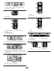
Safety and Instructional Decals Safety decals and instructions are easily visible to the operator and are located near any area of potential danger. Replace any decal that is damaged or lost. 100-1701 1. 2. 3. 4. 5. Crushing hazard—install the cylinder lock and read the instructions before servicing or performing maintenance. Warning—remove the ignition key and lower the loader arms before leaving the machine. Cutting hazard of hand—wait for moving parts to stop.
100-1702 1. Warning—read the Operator’s Manual; maximum load rating of 515 lb. (234 Kg). 98-8235 1. Fast 2. Traction drive 100-1703 3. Slow 1. Speed selector 98-8219 100-1704 1. Read the Operator’s Manual. 2. Place the auxiliary hydraulics in Neutral. 1. Fast 2. Throttle 3. Start the engine. 3. Slow 100-1692 1. Brake engaged 2. Parking brake 93-7814 3. Brake disengaged 1. Entanglement hazard, belt—stay away from moving parts. 93-9084 100-8821 1. Lift point 1.
6-5976 1. Engine coolant under pressure 2. Explosion hazard—read the Operator’s Manual. 3. Warning—do not touch the hot surface. 4. Warning—read the Operator’s Manual. 98-3555 1. Read the instructions before servicing or performing maintenance on the battery. 2. Contains lead; do not discard. 3. Explosion hazard—wear eye protection. 4. Caustic liquid/chemical burn hazard—to perform first aid, flush with water. 5. Fire hazard—no fire, open flames, or smoking. 6.
Setup 3 1 Activating the Battery Installing the Valve Lever No Parts Required Parts needed for this procedure: Procedure 1 The traction unit is shipped with a dry battery. You must purchase bulk electrolyte with 1.260 specific gravity from a local battery supply outlet. Speed selector valve lever Procedure 1. Remove and discard the nut securing the bolt and lock washer to the speed selector lever. Battery terminals or metal tools could short against metal components, causing sparks.
5. Disconnect the negative (black) cable from the negative (-) battery post, if it isn’t already disconnected (Figure 4). Incorrect battery cable routing could damage the tractor and cables causing sparks. Sparks can cause the battery gasses to explode, resulting in personal injury. • Always disconnect the negative (black) battery cable before disconnecting the positive (red) cable. Figure 5 1. Filler caps 2.
15. Secure the battery in the chassis with the bars and nuts removed previously (Figure 4). 16. Connect the positive (red) cable to the positive (+) battery post (Figure 4). Slide the rubber cover over the battery post. 17. Connect the negative (black) cable to the negative (-) battery post (Figure 4). Important: Ensure that the battery cables do not contact any sharp edges or each other. 18. Install the battery cover (Figure 4).
Product Overview 5 15 14 17 20 14 13 22 4 19 6 3 8 4 12 18 11 2 21 16 7 9 1 G005939 10 18 Figure 7 1. 2. 3. 4. 5. 6. Mount plate 7. Wheel Tilt cylinder 8. Lift cylinder Auxiliary hydraulic couplers 9. Operator platform Loader arms 10. Rear access cover (open) Front access cover 11. Engine Fuel tank 12. Air filter 13. 14. 15. 16. 17. 18. Controls 3 1 5 2 19. 20. 21. 22.
Auxiliary Hydraulics Lever Note: The farther you move the traction control levers in either direction, the faster the traction unit will move in that direction. • To operate a hydraulic attachment in forward direction, slowly pull the auxiliary hydraulics lever upward and then rearward. • To operate a hydraulic attachment in reverse direction, slowly pull the auxiliary hydraulics lever upward and then push it forward. This is also called the detent position because it does not require operator presence.
Flow Divider Control Parking Brake The traction unit hydraulics (i.e., the traction drive, loader arms, and attachment tilt) work on a separate hydraulic circuit from the auxiliary hydraulics for powering attachments; however, the two systems share the same hydraulic pumps. Using the flow divider control (Figure 10), you can vary the speed of the traction unit hydraulics by diverting hydraulic flow to the auxiliary hydraulics circuit.
oil as needed. If the problem persists, contact your Authorized Toro Dealer for diagnostics and repair. This light is on when the key is turned to run before starting the engine. The glow plug light will remain on for up to 10 seconds, indicating that the glow plugs are warming the engine. If the glow plug light is on while the engine is running, the glow plugs are broken. Contact your Authorized Toro Dealer for diagnostics and repair.
Stability Data The following tables list the maximum slope recommended for the traction unit in the positions listed in the tables. Slopes over the listed degree may cause the traction unit to become unstable. The data in the tables assume that the loader arms are fully lowered; raised arms may affect the stability. In each attachment manual is a set of three stability ratings, one for each hill position.
Operation Note: Determine the left and right sides of the machine from the normal operating position. Important: Before operating, check the fuel, oil, and coolant level; remove debris from the traction unit; test the parking brake, and check the tire pressure. Also, ensure that the area is clear of people and debris. You should also know and have marked the locations of all utility lines. You could fall off of the platform and be seriously injured during operation.
3. Turn the drain valve until the water runs out of the filter (Figure 13). 9. Slowly pour only enough oil (diesel engine oil, API service CH-4, CI-4, or higher; refer to Servicing the Engine Oil in Maintenance) into the valve cover to raise the level to the upper mark on the dipstick. Note: The fuel filter is located near the bottom of the fuel tank. Important: Do not overfill the crankcase with oil because the engine may be damaged. 10. Replace the filler cap and dipstick.
Important: Do not over fill the radiator. 4. Remove the front access cover. 5. Replace the radiator filler cap, ensuring that it is tightly sealed. 5. Clean the area around the filler neck of the hydraulic tank (Figure 16). 6. Remove the cap from the filler neck and check the fluid level on the dipstick (Figure 16). Removing Debris from the Traction Unit The fluid level should be between the marks on the dipstick.
Checking the Tire Pressure freezing or lower), hydraulic system damage could occur. When starting the engine in cold conditions, allow the engine to run in the middle throttle position for 2 to 5 minutes before moving the throttle to fast (rabbit). Service Interval: Before each use or daily Maintain the air pressure in the tires as specified. Check the tires when they are cold to get the most accurate reading.
Using the Cylinder Locks A child or untrained bystander could attempt to operate the traction unit and be injured. The loader arms may lower when in the raised position crushing anyone under them. Remove the key from the switch when leaving the traction unit, even if just for a few seconds. Install the cylinder locks before performing maintenance that requires raised loader arms.
Important: The attachment should be raised enough to clear the ground, and the mount plate should be tilted all the way back. 6. Stop the engine. 7. Engage the quick attach pins, ensuring that they are fully seated in the mount plate (Figure 23). Important: If the pins do not rotate to the engaged position, the mount plate is not fully aligned with the holes in the attachment receiver plate. Check the receiver plate and clean it if necessary. Figure 21 1. Hydraulic hoses 2. Cylinder locks 3.
Connecting the Hydraulic Hoses Removing an Attachment If the attachment requires hydraulics for operation, connect the hydraulic hoses as follows: 1. Stop the engine. 2. Move the auxiliary hydraulics lever forward, backward, and back to neutral to relieve pressure at the hydraulic couplers. 3. Move the auxiliary hydraulics lever forward into the detent position. 4. Remove the protective covers from the hydraulic couplers on the traction unit. 5.
4 1 2 3 5 G006054 6 Figure 24 1. Thigh support bracket 2. Adjustment plate 3. Thigh support pad 4. Knob and flat washer 5. Carriage bolt 6.
Maintenance Note: Determine the left and right sides of the machine from the normal operating position. Recommended Maintenance Schedule(s) Maintenance Service Interval Maintenance Procedure After the first 8 hours • Replace the hydraulic filter. • Torque the wheel lug nuts to 50 ft-lb (68 N⋅m). After the first 50 hours • Change the engine oil and filter. Before each use or daily • • • • • • • • Drain water from the fuel filter. Check the engine oil level. Check the engine coolant level.
Premaintenance Procedures Opening the Access Covers Removing the Front Access Cover 1. Raise the loader arms and install the cylinder locks. Note: In the case that you need to remove the front access cover without raising the loader arms, be very careful not to damage the cover or hydraulic hoses as you maneuver the cover out from under the arms. Figure 26 1. Rear access cover 2. Locking tabs 2. Stop the engine and remove the key. 3. Release the two locking tabs (Figure 25, top, left tab illustrated). 3.
Lubrication Engine Maintenance Greasing the Traction Unit Servicing the Air Cleaner Service Interval: Before each use or daily Primary Filter: Replace after every 200 operating hours or more often in dusty conditions. Grease all pivot joints every 8 operating hours and immediately after every washing. Safety Filter: Replace after every 600 operating hours. Grease Type: General-purpose grease. Note: Service the air cleaner more frequently if operating conditions are extremely dusty or sandy. 1.
8. Inspect the new filter(s) for damage by looking into the filter while shining a bright light on the outside of the filter. Holes in the filter will appear as bright spots. Inspect the element for tears, an oily film, or damage to the rubber seal. If the filter is damaged do not use it. Components will be hot if the traction unit has been running. If you touch hot components you may be burned. Allow the traction unit to cool before performing maintenance or touching components under the hood. 9.
Fuel System Maintenance 11. Apply a thin coat of new oil to the rubber gasket on the replacement filter (Figure 31). 12. Install the replacement oil filter to the filter adapter. Turn the oil filter clockwise until the rubber gasket contacts the filter adapter, then tighten the filter an additional 1/2 turn (Figure 31). Changing the Fuel Filter Service Interval: Yearly 13. Remove the oil fill cap and slowly pour approximately 80% of the specified amount of oil in through the valve cover.
• After the engine has ceased running due to lack of fuel. 2. Lower the loader arms, stop the engine, and remove the key. • After maintenance has been performed on the fuel system components. 3. Shut off the fuel valve in the hose near the bottom of the fuel tank (Figure 34). 1. Open the rear access cover. 1 2. Place a drain pan under the fuel filter to catch spills. 3. Open the bleed screw on top of the fuel filter to fill the bowl with fuel (Figure 33). 2 Figure 33 1. Fuel filter G003795 2.
Electrical System Maintenance 2 Servicing the Battery 3 Check the electrolyte level in the battery every 75 hours. Always keep the battery clean and fully charged. Use a paper towel to clean the battery case. If the battery terminals are corroded, clean them with a solution of four parts water and one part baking soda. Apply a light coating of grease to the battery terminals to reduce corrosion. 1 G003794 Figure 36 1. Filler caps 2. Upper line Voltage: 12 v, 450 Cold Cranking Amps 3. Lower line 4.
2. Make sure the filler caps are installed in the battery. 3. Charge the battery for 10 to 15 minutes at 25 to 30 amps or 30 minutes at 4 to 6 amps (Figure 37). Do not overcharge the battery. Incorrect battery cable routing could damage the tractor and cables causing sparks. Sparks can cause the battery gasses to explode, resulting in personal injury. 4 • Always disconnect the negative (black) battery cable before disconnecting the positive (red) cable.
Hydraulic System Maintenance Hydraulic fluid escaping under pressure can penetrate skin and cause injury. Fluid injected into the skin must be surgically removed within a few hours by a doctor familiar with this form of injury or gangrene may result. Replacing the Hydraulic Filter Service Interval: After the first 8 hours • Keep your body and hands away from pin hole leaks or nozzles that eject high pressure hydraulic fluid.
Storage After every 25 operating hours, check the hydraulic lines and hoses for leaks, loose fittings, kinked lines, loose mounting supports, wear, weather, and chemical deterioration. Replace all moving hydraulic hoses every 1500 hours or 2 years, which ever comes first. Make necessary repairs before operating. 1. Lower the loader arms, stop the engine, and remove the key. 2. Remove dirt and grime from the external parts of the entire traction unit, especially the engine.
Troubleshooting Problem The starter does not crank Possible Cause 1. The electrical connections are corroded or loose. 1. Check the electrical connections for good contact. 2. A fuse is blown or loose. 3. The battery is discharged. 4. The relay or switch is damaged. 2. Correct or replace the fuse. 3. Charge the battery or replace it. 4. Contact your Authorized Service Dealer. 5. Contact your Authorized Service Dealer. 6. Contact your Authorized Service Dealer. 5. A damaged starter or starter solenoid.
Problem Possible Cause 6. The spark arrestor screen is clogged. 7. The fuel pump is damaged. The engine runs, but knocks or misses. 1. Drain and flush the fuel system; add fresh fuel. 2. Engine overheating. 3. There is air in the fuel. 2. Refer to Engine Overheats. 3. Bleed nozzles and check for air leaks at the fuel hose connections and fittings between the fuel tank and engine. 4. Contact your Authorized Service Dealer. 5. Contact your Authorized Service Dealer. 6.
Problem The engine loses power. Possible Cause 1. The engine load is excessive. 1. Reduce ground speed. 2. The crankcase oil level is incorrect. 3. The air cleaner filters are dirty. 4. Dirt, water, stale fuel, or incorrect fuel is in the fuel system. 5. Engine overheating. 6. The spark arrestor screen is clogged. 2. Fill or drain to the full mark. 3. Service the air filters. 4. Drain and flush the fuel system; add fresh fuel. 5. Refer to Engine Overheats. 6. Clean or replace the spark arrestor screen.
Schematics Electrical Schematic (Rev.
Hydraulic Schematic (Rev.
Notes: 42
Notes: 43