Form No. 3372-635 Rev A Wheelmaster 320-D Compact Utility Loader Model No. 22337CP—Serial No. 312000001 and Up Register at www.Toro.com.
This manual identifies potential hazards and has safety messages identified by the safety alert symbol (Figure 2), which signals a hazard that may cause serious injury or death if you do not follow the recommended precautions. DANGER There may be buried power, gas, and/or telephone lines in the work area. Shock or explosion may occur if you dig into them. Have the property or work area marked for buried lines and do not dig in marked areas.
Safety Engine Maintenance ..................................................27 Servicing the Air Cleaner .........................................27 Servicing the Engine Oil..........................................27 Fuel System Maintenance ...........................................29 Changing the Fuel Filter ..........................................29 Bleeding the Fuel System .........................................29 Draining the Fuel Tank ...........................................
• Read all attachment manuals. • Ensure that the area is clear of other people before • Wear appropriate clothing including hard hat, safety • • • glasses, long pants, safety shoes, and hearing protection. Long hair, loose clothing or jewelry may get tangled in moving parts. Inspect the area where the equipment is to be used and remove all objects such as rocks, toys, and wire which can be thrown by the machine. Use extra care when handling fuels. They are flammable and vapors are explosive.
• • • • • • • • • • • • Keep hands and feet away from moving parts. If possible, traction unit the heavy end. Most other attachments will make the front of traction unit the heavy end. Raising the loader arms on a slope will affect the stability of the machine. Whenever possible, keep the loader arms in the lowered position when on slopes. Removing an attachment on a slope will make the rear of the traction unit heavy.
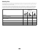
Stability Data The following tables list the maximum slope recommended for the traction unit in the positions listed in the tables. Slopes over the listed degree may cause the traction unit to become unstable. The data in the tables assume that the loader arms are fully lowered; raised arms may affect the stability. In each attachment manual is a set of three stability ratings, one for each hill position.
Slope Indicator G011841 Figure 3 This page may be copied for personal use. 1. To determine the maximum slope you can safely operate the machine on, refer to the Stability Data section. Use the slope indicator to determine the degree of slope of hills before operating. Do not operate this machine on a slope greater than that specified in the Stability Data section. Fold along the appropriate line to match the recommended slope. 2. Align this edge with a vertical surface, a tree, building, fence pole, etc.
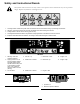
Safety and Instructional Decals Safety decals and instructions are easily visible to the operator and are located near any area of potential danger. Replace any decal that is damaged or lost. 100-1701 1. Crushing hazard—install the cylinder lock and read the instructions before servicing or performing maintenance. 2. Warning—remove the ignition key and lower the loader arms before leaving the machine. 3. Cutting hazard of hand—wait for moving parts to stop. 4.
100-1702 1. Warning—read the Operator's Manual; maximum load rating of 515 lb. (234 Kg). 100-8822 1. Warning—do not carry passengers. 100-1703 1. Speed selector 98-8235 1. Fast 2. Traction drive 3. Slow 100-1704 1. Read the Operator's Manual. 2. Place the auxiliary hydraulics in Neutral. 3. Start the engine. 98-8219 93-7814 1. Fast 2. Throttle 1. Entanglement hazard, belt—stay away from moving parts. 3. Slow 100-1692 100-8821 1. Brake engaged 2. Parking brake 1.
93-9084 2. Tie-down point 1. Lift point 108-4723 1. Auxiliary hydraulics 3. Neutral (off) 2. Locked reverse (detent) 4. Forward 98-4387 1. Warning—wear hearing protection. 106–5976 1. Engine coolant under pressure 3. Warning –do not touch the hot surface. 2. Explosion hazard—read the Operator’s Manual. 4. Warning–read the Operator’s Manual. 98-3555 1. Read the instructions before servicing or performing maintenance on the battery. 2. Contains lead; do not discard. 3.
Setup 3 1 Installing the Battery Installing the Valve Lever Parts needed for this procedure: 1 Maintenance-free battery Parts needed for this procedure: 1 Procedure Speed selector valve lever The traction unit is shipped without a battery. Your dealer will provide a maintenance free battery with the product. Procedure 1. Remove and discard the nut securing the bolt and lock washer to the speed selector lever.
1. Start the engine and run it at half throttle for 5 to 10 minutes to warm it up. WARNING Charging the battery produces gasses that can explode. Important: The engine must be warm before making this adjustment. Never smoke near the battery and keep sparks and flames away from battery. 2. Move the throttle to the Fast position. 3. Using a tachometer and the throttle adjustment screw on the engine (Figure 6), set the engine speed to 3200 RPM maximum, then tighten the jam nut on the adjusting screw. 4.
Product Overview 5 15 14 17 20 4 14 13 22 19 6 3 8 4 12 18 11 2 21 16 7 9 1 G005939 10 18 Figure 7 1. Mount plate 7. Wheel 13. Control panel 19. Parking brake lever 2. Tilt cylinder 8. Lift cylinder 14. Lift points 20. Radiator fill cap 3. Auxiliary hydraulic couplers 9. Operator platform (removable counterweight not shown) 15. Handle 21. Thigh support 10. Rear access cover (open) 16. Battery 22. Flow divider control 4. Loader arms 5. Front access cover 11. Engine 17.
• Note: The farther you move the traction control levers in either direction, the faster the traction unit will move in that direction. To slow or stop, move the traction control levers to neutral. push it forward. This is also called the detent position because it does not require operator presence. Speed Selector Lever WARNING Attachment Tilt Lever If you move the speed selector lever while the traction unit is in motion, the traction unit will either stop suddenly or accelerate quickly.
Figure 10 1. Flow divider control 4. 10 to 11 o'clock position 2. Knob 5. 9 o'clock position Figure 11 1. Parking brake lever—On position 3. 12 o'clock position 2. Parking brake lever—Off position • Move the flow divider control to the twelve o'clock position to provide maximum speed to the traction unit hydraulics. Indicator Lights The indicator lights warn you in the case of a system malfunction and, in the case of the glow plug light, indicate that the glow plugs are on.
This light is on when the key is turned to run before starting the engine. The glow plug light will remain on for up to 10 seconds, indicating that the glow plugs are warming the engine. If the glow plug light is on while the engine is running, the glow plugs are broken. Contact your Authorized Toro Dealer for diagnostics and repair. Specifications Note: Specifications and design are subject to change without notice. Width 40.
Operation Note: Determine the left and right sides of the machine from the normal operating position. Important: Before operating, check the fuel, oil, and coolant level; remove debris from the traction unit; test the parking brake, and check the tire pressure. Also, ensure that the area is clear of people and debris. You should also know and have marked the locations of all utility lines. CAUTION You could fall off of the platform and be seriously injured during operation.
Checking the Engine Coolant Level Service Interval: Before each use or daily The cooling system is filled with a 50/50 solution of water and permanent ethylene glycol antifreeze. Check the level of coolant at the beginning of each day, before starting the engine. WARNING Figure 13 If the engine has been running, the coolant in the radiator will be hot and pressurized. If you remove the cap, it may spray out, causing severe burns. • Do not remove the radiator cap to check coolant levels.
2. Stop the engine and remove the key. 3. Remove the front access cover. 7. If the level is low, add enough fluid to raise it to the proper level. 4. Clean any debris from the grill. 8. Install the cap on the filler neck. 5. Open the rear access cover. 9. Install the front access cover. 10. Remove and store the cylinder locks and lower the loader arms. 6. Wipe away debris from the air cleaner. 7. Clean any debris buildup on the engine with a brush or blower before each use.
Checking the Tire Pressure Note: If outdoor temperature is below freezing, store the traction unit in a garage to keep it warmer and aid in starting. Service Interval: Before each use or daily Maintain the air pressure in the tires as specified. Check the tires when they are cold to get the most accurate reading. Driving the Traction Unit Pressure: 15-20 psi (103-138 kPa) The throttle control regulates the engine speed as measured in rpm (revolutions per minute).
Moving a Non-functioning Traction Unit 2. Raise the loader arms to the fully raised position. Important: Do not tow or pull the traction unit without first opening the tow valves, or the hydraulic system will be damaged. 4. Position a loader arm cylinder lock over each lift cylinder rod (Figure 20). 3. Stop the engine. 5. Secure each loader arm cylinder lock with a clevis pin and cotter pin (Figure 20). 1. Stop the engine. 2.
Using Attachments Installing an Attachment Important: Use only Toro-approved attachments. Attachments can change the stability and the operating characteristics of the traction unit. The warranty of the traction unit may be voided if used with unapproved attachments. Important: Before installing the attachment, ensure that the mount plates are free of any dirt or debris and that the pins rotate freely. If the pins do not rotate freely, grease them. 1.
Connecting the Hydraulic Hoses 2. Stop the engine. If the attachment requires hydraulics for operation, connect the hydraulic hoses as follows: 3. Disengage the quick attach pins by turning them to the outside. 1. Stop the engine. 4. If the attachment uses hydraulics, move the auxiliary hydraulics lever forward, backward, and back to neutral to relieve pressure at the hydraulic couplers. 2.
4 1 2 3 5 G006054 6 Figure 24 1. Thigh support bracket 4. Knob and flat washer 2. Adjustment plate 5. Carriage bolt 3. Thigh support pad 6.
Maintenance Note: Determine the left and right sides of the machine from the normal operating position. Recommended Maintenance Schedule(s) Maintenance Service Interval Maintenance Procedure After the first 8 hours • Replace the hydraulic filter. • Torque the wheel lug nuts to 50 ft-lb (68 N⋅m). After the first 50 hours • Change the engine oil and filter. Before each use or daily • • • • • • • • Drain water from the fuel filter. Check the engine oil level. Check the engine coolant level.
Lubrication Greasing the Traction Unit Service Interval: Before each use or daily Grease all pivot joints every 8 operating hours and immediately after every washing. Grease Type: General-purpose grease. 1. Lower the loader arms and stop the engine. Remove the key. Figure 25 2. Clean the grease fittings with a rag. 3. Connect a grease gun to each fitting (Figure 27 and Figure 28). 4. Pull the cover off of the traction unit. 5.
Engine Maintenance the filter. Holes in the filter will appear as bright spots. Inspect the element for tears, an oily film, or damage to the rubber seal. If the filter is damaged do not use it. Servicing the Air Cleaner 9. If you are replacing the safety filter, carefully slide the new filter into the filter body (Figure 29). Primary Filter: Replace after every 200 operating hours or more often in dusty conditions.
14. Check the oil level; refer to Checking the Engine Oil Level (page 18). 4. Place a pan under the oil drain tube (Figure 30). 15. Slowly add additional oil to bring the level to the upper mark on the dipstick. 16. Replace the fill cap. 17. Close the rear access cover. Figure 30 1. Clamp 2. Oil drain tube 3. Plug 5. Loosen the clamp and remove the plug (Figure 30). 6. When the oil has drained completely, replace the plug and tighten the clamp.
Fuel System Maintenance 1. Open the rear access cover. 2. Place a drain pan under the fuel filter to catch spills. 3. Open the bleed screw on top of the fuel filter to fill the bowl with fuel (Figure 33). Changing the Fuel Filter Service Interval: Yearly Replace the fuel filter yearly. Important: Never install a dirty filter. 1. Lower the loader arms, stop the engine, and remove the key. 2. Shut off the fuel valve on the bottom of the fuel tank (Figure 34). Figure 33 3. Open the rear access cover. 4.
Electrical System Maintenance 1 2 Servicing the Battery Important: The battery you received with your product is a maintenance free battery, and as such you do not need to follow these maintenance procedures. This section details the procedures for maintaining a standard lead acid battery which you may use as a replacement for the original when it wears out. Check the electrolyte level in the battery every 75 hours. Always keep the battery clean and fully charged.
4. Lift the battery off of the platform. Important: Never fill the battery with distilled water while the battery is installed in the traction unit. Electrolyte could be spilled on other parts and cause corrosion. 2 3 5. Clean the top of the battery with a paper towel. 6. Remove the filler caps from the battery (Figure 36). 1 7. Slowly pour distilled water into each battery cell until the electrolyte level is up to the Upper line (Figure 36) on the battery case. G003794 Figure 36 1.
Hydraulic System Maintenance 4 2 3 Replacing the Hydraulic Filter 1 Service Interval: After the first 8 hours Every 400 hours Important: Do not substitute an automotive oil filter or severe hydraulic system damage may result. G003792 Change the hydraulic filter after the first 8 operating hours and then every 400 operating hours thereafter. Figure 37 1. Positive battery post 3. Red (+) charger lead 2. Negative battery post 4. Black (-) charger lead 1. Position traction unit on a level surface.
WARNING Industry Standards API GL-4, AGCO Powerfluid 821 XL, Ford New Holland FNHA-2-C-201.00, Kubota UDT, John Deere J20C, Vickers 35VQ25 and Volvo WB-101/BM. Hydraulic fluid escaping under pressure can penetrate skin and cause injury. Fluid injected into the skin must be surgically removed within a few hours by a doctor familiar with this form of injury or gangrene may result. Note: Many hydraulic fluids are almost colorless, making it difficult to spot leaks.
Checking the Hydraulic Lines Storage Service Interval: Every 25 hours 1. Lower the loader arms, stop the engine, and remove the key. Every 1,500 hours 2. Remove dirt and grime from the external parts of the entire traction unit, especially the engine. Clean dirt and chaff from the radiator. After every 25 operating hours, check the hydraulic lines and hoses for leaks, loose fittings, kinked lines, loose mounting supports, wear, weather, and chemical deterioration.
Troubleshooting Problem The starter does not crank Possible Cause 1. The electrical connections are corroded or loose. 1. Check the electrical connections for good contact. 2. A fuse is blown or loose. 3. The battery is discharged. 4. The relay or switch is damaged. 2. Correct or replace the fuse. 3. Charge the battery or replace it. 4. Contact your Authorized Service Dealer. 5. Contact your Authorized Service Dealer. 6. Contact your Authorized Service Dealer. 5. A damaged starter or starter solenoid.
Problem The engine starts, but does not keep running. Possible Cause 1. The fuel tank vent is restricted. 1. Loosen the cap. If the engine runs with the cap loosened, replace the cap. 2. Dirt or water is in the fuel system. 2. Drain and flush the fuel system; add fresh fuel. 3. Replace the fuel filter. 4. Bleed the nozzles and check for air leaks at fuel hose connections and fittings between the fuel tank and engine. 5. Drain the fuel system and replace the fuel filter.
Problem The engine overheats. Possible Cause 1. More coolant is needed. 1. Check and add coolant. 2. Restricted air flow to the radiator. 2. Inspect and clean the radiator screen with every use. 3. Fill or drain to the full mark. 4. Reduce load; use lower ground speed. 5. Drain and flush the fuel system; add fresh fuel. 6. Contact your Authorized Service Dealer. 7. Contact your Authorized Service Dealer. 8. Contact your Authorized Service Dealer. 9. Contact your Authorized Service Dealer. 3.
Problem Traction unit does not drive. Possible Cause Corrective Action 1. The parking brake is on. 1. Release the parking brake. 2. Hydraulic fluid level low. 3. The tow valves are open. 4. Flow divider valve lever is in 9 o'clock position. 5. Traction pump drive coupler is loose or broken. 6. Pump and/or wheel motor is damaged. 2. Add hydraulic fluid to the reservoir. 3. Close the tow valves. 4. Move lever to 12 o'clock to 10 o'clock position. 5. Contact your Authorized Service Dealer. 6.
Schematics Electrical Schematic (Rev.
Hydraulic Schematic (Rev.
Notes: 41
Notes: 42
Notes: 43
Toro Compact Utility Equipment Warranty A One-Year Limited Warranty Conditions and Products Covered The Toro® Company and its affiliate, Toro Warranty Company, pursuant to an agreement between them, jointly warrant your Toro Compact Utility Equipment (“Product”) to be free from defects in materials or workmanship.