Form No. 3441-289 Rev A TX 427 Compact Tool Carrier Model No. Model No. Model No. Model No. Register at www.Toro.com. Original Instructions (EN) 22321—Serial No. 407400000 and Up 22321G—Serial No. 405700000 and Up 22322—Serial No. 407400000 and Up 22342HD—Serial No.
This product complies with all relevant European directives; for details, please see the separate product specific Declaration of Conformity (DOC) sheet. Visit www.Toro.com for product safety and operation training materials, accessory information, help finding a dealer, or to register your product.
Contents Replacing the Hydraulic Filter ........................... 44 Changing the Hydraulic Fluid ............................ 45 Cleaning .............................................................. 46 Removing Debris .............................................. 46 Cleaning the Chassis........................................ 46 Storage ................................................................... 48 Storage Safety.................................................. 48 Storage....................
Safety Improperly using or maintaining this machine can result in injury. To reduce the potential for injury, comply with these safety instructions and always pay attention to the safety-alert symbol , which means Caution, Warning, or Danger—personal safety instruction. Failure to comply with these instructions may result in personal injury or death. General Safety DANGER There may be buried utility lines in the work area. Digging into them may cause a shock or an explosion.
Safety and Instructional Decals Safety decals and instructions are easily visible to the operator and are located near any area of potential danger. Replace any decal that is damaged or missing. decalbatterysymbols Battery Symbols Some or all of these symbols are on your battery. 1. Explosion hazard 6. Keep bystanders away from the battery. 2. No fire, open flame, or smoking 7. Wear eye protection; explosive gases can cause blindness and other injuries. 3. Caustic liquid/chemical burn hazard 4.
decal115-4020 115-4020 1. Turn right 3. Reverse 2. Forward decal115-4859 115-4859 4. Turn left 1. Disengaged 3. Engaged 2. Parking brake decal115-4855 115-4855 1. Hot surface/burn hazard—wear protective gloves when handling the hydraulic couplers and read the Operator's Manual for information on handling hydraulic components. decal115-4861 115-4861 1. Auxiliary hydraulics 3. Forward 2. Locked reverse (detent) 4. Neutral (off) decal115-4857 115-4857 1. Lower the loader arms. 2.
decal140-5728 140-5728 1. Read the Operator’s Manual. decal115-4860 115-4860 1. Warning—read the Operator's Manual. 2. Warning—lower the loader arms, engage the parking brake, shut off the engine, and remove the key before leaving the machine. 3. Crushing hazard from above—install the cylinder lock and read the Operator’s Manual before performing maintenance. 4. Cutting hazard of hands or feet—wait for all moving parts to stop; stay away from moving parts; keep all guards and shields in place. 5.
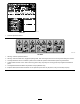
decal138-0799 138-0799 9. Hour meter 1. Read the Operator’s Manual stored in your machine. 2. Fast 10. Engine—start 3. Throttle 11. Engine—run 4. Slow 12. Engine—shut off 5. Choke—on 13. Warning—do not operate this machine unless you are trained. 6. Choke—off 14. Electrical shock hazard, overhead power lines—watch for overhead power lines. 7. Fuel 15. Tipping hazard—move the traction unit with the heavy end uphill; carry loads low; do not drive the machine with the load raised. 16.
Product Overview g005550 Figure 3 1. Track 5. Loader arms 9. Mount plate 2. Track-adjustment chamber 6. Hood 3. Lift cylinder 7. Auxiliary hydraulic couplers 11. Control panel 4. Cylinder lock 8. Tilt cylinder 10. Tie-down/lift loop 13. Fuel tank 14. Reverse-safety plate 12. Rear-access cover Controls Key Switch Become familiar with all the controls (Figure 4) before you start the engine and operate the traction unit.
Traction Control • To turn right, rotate the traction control clockwise (Figure 8). g008128 g008131 Figure 5 Figure 8 1. Reference bar 2. Traction control • To turn left, rotate the traction control counterclockwise (Figure 9). • To move forward, move the traction control forward (Figure 6). g008132 Figure 9 g008129 • To stop the machine, release the traction control Figure 6 (Figure 5).
Loader Arm/Attachment-Tilt Lever • To tilt the attachment forward, slowly move the lever to the right (Figure 10). • To tilt the attachment rearward, slowly move the lever to the left (Figure 10). • To lower the loader arms, slowly move the lever forward (Figure 10). • To raise the loader arms, slowly move the lever g029981 rearward (Figure 10). Figure 11 • To lower the loader arms to a detent (float) 1. Loader arm/attachment-tilt lever position, push the lever fully forward (Figure 10). 2.
Hour Meter/Tachometer Fuel Gauge When the engine is off, the hour meter/tachometer displays the number of hours of operation logged on the machine. When the engine is running, it displays the speed of the engine in revolutions per minute (rpm). This gauge measures the amount of fuel in the fuel tank(s). After 50 hours and then every 100 hours thereafter (i.e., 150, 250, 350, etc.) the screen displays CHG OIL to remind you to change the engine oil.
Specifications Attachments/Accessories Note: Specifications and design are subject to A selection of Toro approved attachments and accessories is available for use with the machine to enhance and expand its capabilities. Contact your Authorized Service Dealer or authorized Toro distributor or go to www.Toro.com for a list of all approved attachments and accessories. change without notice.
Fuel Safety Operation • Use extreme care when handling fuel. It is flammable and its vapors are explosive. Before Operation • Extinguish all cigarettes, cigars, pipes, and other sources of ignition. Note: Determine the left and right sides of the • Use only an approved fuel container. • Do not remove the fuel cap or fill the fuel tank machine from the normal operating position. while the engine is running or hot. Before Operation Safety • Do not add or drain fuel in an enclosed space.
Using Stabilizer/Conditioner Performing Daily Maintenance Use fuel stabilizer/conditioner in the machine to keep the fuel fresh longer when used as directed by the fuel-stabilizer manufacturer. Before starting the machine each day, perform the Each Use/Daily procedures listed in the Maintenance (page 22). Important: Do not use fuel additives containing methanol or ethanol. Add the amount of fuel stabilizer/conditioner to fresh fuel as directed by the fuel-stabilizer manufacturer.
• Never carry passengers and keep pets and machine the heavy end. Most other attachments make the front of machine the heavy end. bystanders away from the machine. • Raising the loader arms on a slope affects the • Operate the machine only in good light, keeping stability of the machine. Keep the loader arms in the lowered position when on slopes. away from holes and hidden hazards.
Shutting Off the Engine Starting the Engine 1. Ensure that the auxiliary hydraulics lever is in the NEUTRAL position. Park the machine on a level surface, engage the parking brake (if equipped), and lower the loader arms. 2. Move the choke lever fully forward if you are starting a cold engine. Ensure that the auxiliary hydraulics lever is in the NEUTRAL position. 3. Move the throttle lever 3/4 of the way to the FAST position. 1. Stand on the platform (if equipped on your machine). 2. 3.
g003710 Figure 15 1. Mount plate 5. 2. Receiver plate Raise the loader arms while tilting back the mount plate at the same time. Important: Raise the attachment enough to clear the ground and tilt the mount plate all the way back. 6. Shut off the engine and remove the key. 7. Engage the quick-attach pins, ensuring that they are fully seated in the mount plate (Figure 16). g003711 Figure 16 1. Quick-attach pins (engaged position) Important: If the pins do not rotate to the 3. Engaged position 2.
Removing an Attachment Connecting the Hydraulic Hoses WARNING Hydraulic fluid escaping under pressure can penetrate skin and cause injury. Fluid injected into the skin must be surgically removed within a few hours by a doctor familiar with this form of injury; otherwise, gangrene may result. • Ensure that all hydraulic-fluid hoses and lines are in good condition and all hydraulic connections and fittings are tight before applying pressure to the hydraulic system.
3. Selecting a Trailer Using a wrench, turn the tow valves on the hydraulic pumps twice counter-clockwise (Figure 17). WARNING Loading a machine onto a trailer or truck increases the possibility of tip-over and could cause serious injury or death (Figure 18). • Use only full-width ramps. • Ensure that the length of ramp is at least 4 times as long as the height of the trailer or truck bed to the ground. This ensures that ramp angle does not exceed 15 degrees on flat ground. g004181 Figure 17 1.
Loading the Machine WARNING Loading a machine onto a trailer or truck increases the possibility of tip-over and could cause serious injury or death. • Use extreme caution when operating a machine on a ramp. • Load and unload the machine with the heavy end up the ramp. • Avoid sudden acceleration or deceleration while driving the machine on a ramp as this could cause a loss of control or a tip-over situation. g242654 Figure 20 1. Tie-down loops 1.
Maintenance Note: Determine the left and right sides of the machine from the normal operating position. Important: If you must tilt the machine more than 25°, clamp off the vent hose on the top of the fuel tank(s) to prevent fuel from fouling the carbon canister. Maintenance Safety CAUTION If you leave the key in the switch, someone could accidently start the engine and seriously injure you or other bystanders. Remove the key from the switch before you perform any maintenance.
Maintenance Service Interval Maintenance Procedure Every 100 hours • Change the engine oil. (Service more frequently if conditions are extremely dusty or sandy.) • Check and adjust the track tension. • Check the hydraulic lines for leaks, loose fittings, kinked lines, loose mounting supports, wear, weather, and chemical deterioration. • Check for dirt buildup in the chassis. Every 200 hours • Replace the carbon-canister air filter (Service more frequently if conditions are extremely dusty or sandy).
Pre-Maintenance Procedures Removing and Storing the Cylinder Lock Important: Remove the cylinder lock from the rod and fully secure it in the storage position before operating the machine. Using the Cylinder Lock 1. Start the engine. 2. Raise the loader arms to the fully raised position. The loader arms may lower when in the raised position, crushing anyone under them. 3. Shut off the engine and remove the key. 4. Remove the lynch pin securing the cylinder lock.
Opening the Rear-Access Cover Opening the Hood 1. Loosen the hood-locking screw (Figure 23) 1. Unscrew the 2 hand knobs securing the rear-access cover to the machine (Figure 25). g004185 Figure 25 1. Hand knobs 2. g009691 Tilt the rear-access cover down and remove it to access the internal components (Figure 25). Figure 23 1. Hood 3. Hood-locking screw Closing the Rear-Access Cover 2. Hood-latch lever 2. Turn the hood latch clockwise (Figure 23). 3. Swing the hood up (Figure 23). 4.
Installing the Side Screens Slide the side screens into place in the slots in the front screen and frame. Removing the Front Screen CAUTION If the engine has been running, the heat shield will be very hot and could burn you. Allow the machine to cool completely before touching the heat shield. 1. Open the hood and remove both side screens. 2. Loosen the bolts securing the weights (Figure 27). g004188 Figure 28 1. Front screen 6. 2.
11. Tighten the bolts securing the front weights (Figure 27). 12. Install the side screens and close the hood. Lubrication Greasing the Machine Service Interval: Before each use or daily (Grease immediately after every washing.) Grease Type: General-purpose grease 1. Park the machine on a level surface, engage the parking brake (if equipped), and lower the loader arms. 2. Shut off the engine and remove the key. 3. Clean the grease fittings with a rag. 4.
Engine Maintenance Engine Safety • Shut off the engine before checking the oil or adding oil to the crankcase. • Do not change the engine governor setting or overspeed the engine. • Keep your hands, feet, face, clothing, and other body parts away from the muffler and other hot surfaces. g031236 Figure 32 Servicing the Air Cleaner Service Interval: Before each use or daily—Check the air-filter-service indicator.
Replacing the Carbon-Canister Purge-Line Filter Important: Do not press on the soft inside area of the filter. 4. Install the air-cleaner cover with the dust cap oriented downward and secure the latches (Figure 32). 5. Close the hood. Service Interval: Every 200 hours—Replace the carbon-canister purge-line filter (Service more frequently when using the vibratory-plow attachment). Note: Check the purge-line filter occasionally for dirt. If the filter looks dirty, replace it.
Engine-Oil Specifications Oil Type: Detergent oil (API service SG, SH, SJ, or higher) Crankcase Capacity: with filter, 2.0 L (2.1 US qt) Viscosity: See table below g004173 Figure 36 1. Fill cap 9. 2. Valve cover Slowly pour only enough oil into the valve cover to raise the level to the F (Full) mark. Important: Do not overfill the crankcase with oil to prevent damaging the engine. g000650 Figure 34 Replace the fill cap and dipstick. 11. Close the hood.
Servicing the Spark Plug(s) 7. Check the oil level. 8. Slowly add additional oil to bring the level to the F (Full) mark on the dipstick. 9. Replace the fill cap. Service Interval: Every 200 hours—Check the spark plug(s). Every 500 hours—Replace the spark plug. Ensure that the air gap between the center and side electrodes is correct before installing each spark plug. Use a spark-plug wrench for removing and installing each spark plug and a gapping tool/feeler gauge to check and adjust the air gap.
Checking the Spark Plug Fuel System Maintenance Important: Do not clean the spark plug(s). Always replace the spark plug(s) when it has a black coating, worn electrodes, an oily film, or cracks. DANGER In certain conditions, fuel is extremely flammable and highly explosive. A fire or explosion from fuel can burn you and others and can damage property. • Drain fuel from the fuel tanks when the engine is cold. Do this outdoors in an open area. Wipe up any fuel that spills.
Electrical System Maintenance Important: Never install a dirty filter. 9. Move the hose clamps close to the filter. 10. Remove the clamp blocking fuel flow and open the fuel valves. 11. Secure the tank cap. Electrical System Safety 12. Replace the side screen and close the hood. • Disconnect the battery before repairing the Draining the Fuel Tank 1. Park the machine on a level surface, engage the parking brake, and lower the loader arms. 2. Shut off the engine and remove the key. 3.
Charging the Battery Important: Always keep the battery fully charged (1.265 specific gravity). This is especially important to prevent battery damage when the temperature is below 0°C (32°F). 1. Remove the battery from the machine; refer to Removing the Battery (page 33). 2. Charge the battery for 10 to 15 minutes at 25 to 30 A or 30 minutes at 4 to 6 A (Figure 44). Do not overcharge the battery. g005293 Figure 43 1. Battery 4. Rubber cover 2. Bar 5. Negative cable 3. Positive cable 5.
Installing the Battery Drive System Maintenance 1. Using the fasteners previously removed, install the positive (red) battery cable to the positive (+) battery terminal (Figure 43). 2. Slide the red terminal boot onto the positive battery post. Servicing the Tracks 3. Using the fasteners previously removed, install the negative (black) battery cable to the negative (-) battery terminal (Figure 43). Service Interval: After the first 50 hours—Check and adjust the track tension. 4.
g004202 g004200 Figure 47 Figure 45 1. Track 2. Drive sprocket 3. Road wheels 4. Tension wheel 1. Locking bolt 3. Tension tube 2. Tensioning screw 4. Tension wheel 5. Using a 1/2-inch drive ratchet, turn the tensioning screw counterclockwise until the distance between the tension nut and the back of the tension tube (Figure 46) is 7 cm (2-3/4 inches). 6. Align the closest notch in the tension screw to the locking bolt hole and secure the screw with the locking bolt and nut (Figure 47). 7.
15. Repeat steps 3 through 14 to replace the other track. Replacing Wide-Width Tracks When the tracks are badly worn, replace them. Note: You have wide-width tracks if the front tension wheels are mounted on the sides of the end of the tension tube (Figure 49). g004203 Figure 48 1. Track Park the machine on a level surface, engage the parking brake, and lower the loader arms. 2. Shut off the engine and remove the key. 3.
9. Remove the nut securing the inner tension wheel and remove the wheel (Figure 49). 3. 10. Pull the 4 large washers out of the 2 wheels, 1 on each side of each wheel. 11. Clean the old grease and dirt out of the area between where the washers were installed and the bearings inside the wheels, then fill this area on each side of each wheel with grease. 12. Install the large washers on the wheels over the grease. 13.
Brake Maintenance Belt Maintenance Testing the Parking Brake Inspecting and Replacing the Drive Belt Service Interval: Before each use or daily 1. Engage the parking-brake; refer to Parking-Brake Lever (page 12). 2. Start the engine. 3. Slowly attempt to drive the machine forward or rearward. 4. If the machine moves, contact your Authorized Service Dealer for service. Service Interval: Every 25 hours—Inspect the drive belt for wear or damage. Every 200 hours—Replace the drive belt.
g243518 Figure 53 Spring cover not shown 1. Idler-pulley assembly 6. 2. Drive-belt routing Remove the belt from the 3 pulleys (Figure 54). g005547 Figure 52 1. Spring-removal tool 4. Idler pulley 2. Drive belt 5. Engine (see-through for illustrative purposes) g005549 3. Idler pulley spring (spring cover not shown) 5. Figure 54 Spring cover not shown Remove the idler pulley spring from the idler-pulley assembly (Figure 53). 7. Install a new drive belt around the 3 pulleys (Figure 53). 8.
Controls System Maintenance Adjusting the Controls The factory adjusts the controls before shipping the machine. However, after many hours of use, you may need to adjust the traction control alignment, the NEUTRAL position of the traction control, and the tracking of the traction control in the full forward position. g004191 Figure 56 1. Traction control Important: To adjust the controls properly, 5. complete each procedure in the order listed. 2.
Adjusting the Tracking of the Traction Control, Full Forward Position If the machine does not drive straight when you hold the traction control against the reference bar, complete the following procedure: 1. Drive the machine with the traction control against the reference bar, noting which direction the traction unit veers. 2. Release the traction control. 3.
Hydraulic-Fluid Specifications Hydraulic System Maintenance Hydraulic Tank Capacity: 45.4 L (12 US gallons) Hydraulic System Safety Use only 1 of the following fluids in the hydraulic system: • Seek immediate medical attention if fluid is injected • Toro Premium Transmission/Hydraulic Tractor into skin. Injected fluid must be surgically removed within a few hours by a doctor.
Checking the Hydraulic-Fluid Level Replacing the Hydraulic Filter Service Interval: Every 25 hours Service Interval: After the first 8 hours Every 200 hours Check the hydraulic-fluid level before the engine is first started and after every 25 operating hours. Important: Do not substitute an automotive oil filter; otherwise, severe hydraulic system damage may result. Refer to Hydraulic-Fluid Specifications (page 43) for hydraulic-fluid specifications. Important: Always use the correct hydraulic 1.
Changing the Hydraulic Fluid Service Interval: Every 400 hours/Yearly (whichever comes first) 1. Park the machine on a level surface, remove any attachment, and engage the parking brake. 2. Raise the loader arms and install the cylinder lock. 3. Shut off the engine, remove the key, and allow the engine to cool. 4. Open the hood and remove the left side screen. 5. Remove the hydraulic-tank cap and dipstick (Figure 63). g004213 Figure 64 1. Drain plug 7.
Cleaning the Chassis Cleaning Service Interval: Every 100 hours—Check for dirt buildup in the chassis. Removing Debris Using a flashlight, open the hood and inspect the area under the engine regularly. When the debris is 2.
19. Connect the fuel line and remove the clamp. 20. Secure the tank cap and tighten it until it clicks. 21. On the right side of the tank, connect the orange wire to the center post and the black wire to the outside post (Figure 66). 22. Slide the tank all the way into the machine. Important: The fuel line and wires must be away from the engine pulleys and the frame. g013123 Figure 66 1. Black wire 2. Orange wire 4. Vent hose 5. To the carbon canister 3. Fuel-tank-vent fitting 13.
Storage use an alcohol-based stabilizer (ethanol or methanol). Storage Safety Note: A fuel stabilizer/conditioner is most effective when you mix it with fresh fuel and use it at all times. • Shut off the engine, remove the key, wait for all moving parts to stop, and allow the machine to cool before storing it. B. Run the engine to distribute conditioned fuel through the fuel system for 5 minutes. • Do not store the machine or fuel near flames. C.
Troubleshooting Problem The engine does not start, starts hard, or fails to keep running. Possible Cause 1. The starting procedure is incorrect. 1. Use the correct starting procedure. 2. The fuel tank is empty. 3. The choke is not engaged. 4. The air cleaner is dirty. 2. Fill the tank with fresh fuel. 3. Engage the choke. 4. Clean or replace the air-cleaner elements. 5. Install the wires on the spark plugs. 5. The spark plug wires are loose or disconnected. 6.
Notes:
European Privacy Notice The Information Toro Collects Toro Warranty Company (Toro) respects your privacy. In order to process your warranty claim and contact you in the event of a product recall, we ask you to share certain personal information with us, either directly or through your local Toro company or dealer. The Toro warranty system is hosted on servers located within the United States where privacy law may not provide the same protection as applies in your country.
California Proposition 65 Warning Information What is this warning? You may see a product for sale that has a warning label like the following: WARNING: Cancer and Reproductive Harm—www.p65Warnings.ca.gov. What is Prop 65? Prop 65 applies to any company operating in California, selling products in California, or manufacturing products that may be sold in or brought into California.