Form No. 3438-963 Rev B TX 1300 Compact Tool Carrier Model No. 22370—Serial No. 400000000 and Up Register at www.Toro.com.
This product complies with all relevant European directives; for details, please see the separate product specific Declaration of Conformity (DOC) sheet. Visit www.Toro.com for product safety and operation training materials, accessory information, help finding a dealer, or to register your product.
Draining the Fuel Tank(s).................................. 50 Electrical System Maintenance ........................... 51 Electrical System Safety ................................... 51 Using the Battery-Disconnect Switch ................ 51 Servicing the Battery......................................... 51 Jump-Starting the Machine............................... 53 Servicing the Fuses .......................................... 55 Drive System Maintenance ..................................
Safety • Keep your hands and feet away from the moving This machine has been designed in accordance with ISO 20474-15:2019. • Do not operate the machine without the guards General Safety • Keep bystanders and pets away from the machine. components and attachments. and other safety protective devices in place and working on the machine. • Stop the machine, shut off the engine, and remove the key before servicing, fueling, or unclogging the machine.
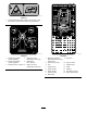
Safety and Instructional Decals Safety decals and instructions are easily visible to the operator and are located near any area of potential danger. Replace any decal that is damaged or missing. decal115-4855 115-4855 1. Hot surface/burn hazard—wear protective gloves when handling the hydraulic couplers and read the Operator's Manual for information on handling hydraulic components. decalbatterysymbols Battery Symbols Some or all of these symbols are on your battery. 1. Explosion hazard 6.
decal117-3276 117-3276 1. Engine coolant under pressure 3. Warning—do not touch the hot surface. 2. Explosion hazard—read the Operator's Manual. 4. Warning—read the Operator's Manual. decal125-6694 125–6694 1. Tie down location decal120-0625 120-0625 1. Pinch point, hand—keep hands away. decal125-8483 125-8483 1. Hydraulic fluid; read the Operator’s Manual. decal122-1925 122-1925 1. Torque to 2.82 to 3.16 N∙m (25 to 28 in-lb) decal125-4967 125-4967 1.
decal139-1159 139-1159 1. Warning—keep bystanders away. decal139-1162 decal131-8026 139-1162 131-8026 1. Battery power—disconnect 3. On 2. Off 4. Read the Operator's Manual. 1. Warning—read the Operator’s Manual for the bucket maximum weight limit. 2. Tipping hazard—do not drive the machine with the load raised or the arms extended; carry the load close to the ground with the arms retracted when driving.
decal139-1173 139-1173 1. High-pressure fluid hazard, injection into the body—read the Operator’s Manual before performing maintenance. decal145-4273 decal145-4274 145-4273 1. Retract the hydraulic cylinder (optional) 4. Extend the arms (telescoping model only) 2. Extend the hydraulic cylinder (optional) 5. Attachment flow—Reverse 145-4274 9. Engine oil 1. Read the Operator’s Manual before performing maintenance. 10. Engine coolant 2. Check every 8 hours 3. Attachment flow—Forward 6.
decal131-0708 131-0708 3. Move rearward 4. Turn right 1. Move forward 2. Turn left decal144-4253 144-4253 1. Parking brake—engaged 5. Engine—stop 2. Parking brake—disengaged 6. Engine—run 3. Fast 7. Engine—start 4. Slow 8.
decal145-0637 145-0637 1. Warning—read the Operator's Manual. 7. Cutting/severing hazard of hand or foot—wait for all moving parts to stop before servicing; keep away from moving parts; keep all guards and shields in place. 2. Warning—receive training before operating the machine. 8. Explosion hazard; electrocution hazard—call the local utilities hotline before beginning work in an area. 3. Warning—wear hearing protection. 9.
Product Overview g318043 Figure 3 1. Hood 5. Lower loader arm 9. Control panel 2. Auxiliary hydraulic couplers 6. Upper loader arm 10. Hydraulic tank 14. Tie-down point 3. Mount plate 7. Track 15. Fuel tank 4. Lift point 8. Cylinder lock 11. Auxiliary hydraulics lock switch 12. Operator platform 11 13.
Reference Bar Controls When driving the traction unit, use the reference bar as a handle and a leverage point for controlling the traction control and the joystick lever. To ensure smooth, controlled operation, do not take your hands off the reference bars while operating the machine. Control Panel Become familiar with all the controls before you start the engine and operate the traction unit. Traction Control g029289 Figure 5 1. Reference bar 2.
Loader Arm/Attachment-Tilt Lever • To turn right, rotate the traction control clockwise. Slowly move the lever to operate the loader arms and tilt the attachment. Note: The detent (float) position allows attachments such as the leveler and the hydraulic blade to follow the contours of the ground (i.e., float) when grading. g264833 Figure 8 • To turn left, rotate the traction control counterclockwise. g264832 Figure 9 g358629 Figure 10 • To stop the machine, release the traction control.
Loader-Valve Lock Joystick Controls The loader-valve lock secures the loader arm/attachment-tilt lever so that you cannot push it forward. This helps to ensure that no one accidentally lowers the loader arms during maintenance. Secure the loader valve with the lock, in addition to the cylinder locks, any time you need to shut off the machine with the loader arms raised. Refer to Using the Cylinder Locks (page 42).
Fuel Gauge InfoCenter Icon Descriptions This gauge measures the amount of fuel in the fuel tank(s). Menu access Next Previous Scroll down g371278 Enter Figure 14 Change the next value in the list InfoCenter Display Increase The InfoCenter LCD display shows information about your machine, such as the operating status, various diagnostics and other information about the machine. There is a splash screen and main information screen of the InfoCenter.
Using the Menus InfoCenter Icon Descriptions (cont'd.) To access the InfoCenter menu system, press the menu access button while at the main screen. This will bring you to the main menu. Refer to the following tables for a synopsis of the options available from the menus: Parking brake Engine Main Menu Glow plugs Menu Item Description Faults The Faults menu contains a list of the recent machine and engine faults.
Service Settings Menu Item Description Menu Item Description Hours Lists the total number of hours that the machine, engine, and auxiliary hydraulics have been on, as well as the number of hours for engine service and hydraulic service. Units Controls the units used on the InfoCenter; the menu choices are Imperial or Metric. Language Controls the language used on the InfoCenter.
2. Specifications In the SETTINGS MENU, scroll down to the PROTECTED MENU and press the right button. Note: Specifications and design are subject to change without notice. Width Length Height Weight Operating capacity (35% of tipping capacity1) • Arms retracted g364601 Figure 17 3. • Arms extended Tipping capacity1 • Arms retracted To enter the PIN code, press the center button until the correct first digit appears, then press the right button to move on to the next digit.
Fuel Safety Operation • Use extreme care when handling fuel. It is Note: Determine the left and right sides of the machine from the normal operating position. • Before Operation • • Before Operation Safety • • General Safety • • Never allow children or untrained people to operate or service the machine. Local regulations may restrict the age or require certified training of the operator. The owner is responsible for training all operators and mechanics.
Biodiesel Ready Performing Daily Maintenance This machine can also use a biodiesel blended fuel of up to B5 (5% biodiesel, 95% petrodiesel). The petrodiesel portion should be low or ultra low sulfur. Observe the following precautions: Before starting the machine each day, perform the Each Use/Daily procedures listed in the Maintenance (page 40).
Slope Safety • Wear appropriate clothing including eye protection, long pants, substantial slip-resistant footwear, and hearing protection; also wear a respirator or dust mask in dusty conditions. Tie back long hair and do not wear loose clothing or loose jewelry. • Operate the machine up and down slopes with the heavy end of the machine uphill. Weight distribution changes with attachments.
Starting the Engine The machine could suddenly roll over if a track goes over the edge or the edge caves in. Maintain a safe distance between the machine and any hazard. 1. Ensure that the battery-disconnect switch is in the ON position; refer to Using the Battery-Disconnect Switch (page 51). 2. Ensure that the traction-control is in the NEUTRAL position. 3. Insert the key into the key switch and turn it to the ON position. 4. Turn the key to the START position.
Shutting Off the Engine 1. Park the machine on a level surface and lower the loader arms. 2. Disengage the auxiliary hydraulics. 3. Set the throttle to low idle. 4. If the engine has been working hard or is hot, let it idle for 5 minutes before turning the key switch to the OFF position. Note: This helps to cool the engine before you 5. g003710 Figure 20 shut it off. In an emergency, you can shut off the engine immediately. 1.
CAUTION Hydraulic couplers, hydraulic lines/valves, and hydraulic fluid may be hot. If you contact hot components, you may be burned. • Wear gloves when operating the hydraulic couplers. • Allow the machine to cool before touching hydraulic components. • Do not touch hydraulic fluid spills. If the attachment requires hydraulics for operation, connect the hydraulic hoses as follows: 1. Shut off the engine and remove the key. 2. Remove the protective covers from the hydraulic connectors on the machine. 3.
Removing an Attachment Understanding the Smart Load System 1. Park the machine on a level surface. 2. Lower the attachment to the ground. 3. Shut off the engine and remove the key. 4. Disengage the quick-attach pins by turning them to the outside. The Smart Load system also measures the hydraulic pressure in the loader arm cylinders to determine the maximum reach.
Diesel Particulate Filter (DPF) Regeneration Understanding DPF Regeneration The diesel particulate filter (DPF) is part of the exhaust system. The diesel-oxidation catalyst of the DPF reduces harmful gasses, and the soot filter removes soot from the engine exhaust. The DPF regeneration process uses heat from the engine exhaust to incinerate the soot accumulated on the soot filter, converting the soot to ash, and clears the channels of the soot filter so that filtered engine exhaust flows out the DPF.
DPF Soot Accumulation • Over time, the diesel particulate filter accumulates soot in the soot filter. The computer for the engine monitors the soot level in the DPF. • When enough soot accumulates, the computer informs you that it is time to regenerate the DPF. • DPF regeneration is a process that heats the DPF to convert the soot to ash. • In addition to the warning messages, the computer reduces the power produced by the engine at different soot-accumulation levels.
DPF Ash Accumulation • The lighter ash is discharged through the exhaust system; the heavier ash collects in the soot filter. • Ash is a residue of the regeneration process. Over time, the diesel particulate filter accumulates ash that does not discharge with the engine exhaust. • The computer for the engine calculates the amount of ash accumulated in the DPF.
Types of DPF Regeneration Types of DPF regeneration that are performed while the machine is operating: Type of Regeneration Conditions that cause DPF regeneration DPF description of operation Passive Occurs during normal operation of the machine at high-engine speed or high-engine load • The InfoCenter does not display an icon indicating passive regeneration. • During passive regeneration, the DPF processes high-heat exhaust gasses, oxidizing harmful emissions, and burning soot to ash.
Types of DPF regeneration that require you to park the machine: (cont'd.) Type of Regeneration Conditions that cause DPF regeneration DPF description of operation Recovery Occurs because the operator ignored requests for a parked regeneration and continued operating the machine, adding more soot to the DPF • When the reset-standby/parked or recovery or ADVISORY #190 regeneration icon displays in the InfoCenter, a recovery regeneration is requested.
Passive DPF Regeneration DPF Operation Table • Passive regeneration occurs as part of normal State Description Normal The DPF is in normal-operating mode—passive regeneration. Assist Regen Reset Stby engine operation. • While operating the machine, run the engine at full-engine speed and high load when possible to promote DPF regeneration. The engine computer is performing an assist regeneration.
Periodic Reset Regeneration Allowing a Reset Regeneration If the engine has not completed a successful Reset, Parked, or Recovery regeneration in the previous 100 hours of engine operation, the engine computer will attempt to perform a reset regeneration. The InfoCenter displays the high exhaust-temperature icon when the reset regeneration is in process. Note: If Inhibit Regen is set to ON, the InfoCenter displays ADVISORY #185 .
Parked or Recovery Regeneration DPF Status-Limitation • When the engine computer requests either a • If the engine computer requests a parked regeneration or is processing a parked regeneration, the PARKED REGEN option locks and the lock icon appears on the screen. parked regeneration or a recovery regeneration, the regeneration request icon InfoCenter.
1. Ensure that the machine has at least the specified amount fuel in the tank for the type of regeneration you are performing: 8. At the INITIATE DPF REGEN screen, press the right button to continue. • Parked Regeneration: 1/4 tank of fuel • Recovery Regeneration: 1/2 tank of fuel 2. Park the machine on a level surface, in an area outside away from combustible materials. 3. Engage the parking brake and lower the loader arms. 4. Set the throttle to the low IDLE position. 5.
11. The engine computer checks the engine state and fault information. The InfoCenter may display the following messages: Message 13. Corrective Action When the engine computer completes a parked or recovery regeneration, the InfoCenter displays ADVISORY #183; if it fails, the InfoCenter displays ADVISORY #184. Press the left button to exit to the home screen.
Moving a Non-Functioning Machine After Operation After Operation Safety Important: Do not tow or pull the machine without first opening the tow valves, or you will damage the hydraulic system. General Safety • Engage the parking brake (if equipped), lower the loader arms, shut off the engine, remove the key, wait for all movement to stop, and allow the machine to cool before adjusting, cleaning, storing, or servicing it. 1. Shut off the engine and remove the key. 2.
6. Tighten the nut to release the brake. you or bystanders avoid injury. Refer to your local ordinances for trailer and tie-down requirements. WARNING Driving on the street or roadway without turn signals, lights, reflective markings, or a slow-moving-vehicle emblem is dangerous and can lead to accidents causing personal injury. Do not drive the machine on a public street or roadway. g370392 Figure 50 Selecting a Trailer 7. Remove the front cover; Removing the Front Cover (page 44). 8.
Loading the Machine Important: Do not use the tie-down loops to lift the machine. WARNING Loading or unloading a machine onto a trailer or truck increases the possibility of tip-over and could cause serious injury or death. • Use extreme caution when operating a machine on a ramp. • Load and unload the machine with the heavy end up the ramp. • Avoid sudden acceleration or deceleration while driving the machine on a ramp as this could cause a loss of control or a tip-over situation. g318338 Figure 54 1.
Lifting the Machine Remove any attachments and lift the machine using the 4 lift points. Do not exceed a 30-degree angle when lifting the machine; use the minimum chain lengths provided below. g375790 Figure 56 1. Chain length for rear lift point (2)—143.0 cm (56.3 inches) 2. Chain length for front lift point (2)—223.2 cm (87.
Maintenance Note: Determine the left and right sides of the machine from the normal operating position. Maintenance Safety CAUTION If you leave the key in the switch, someone could accidently start the engine and seriously injure you or other bystanders. Remove the key from the switch before you perform any maintenance.
Maintenance Service Interval Maintenance Procedure Every 100 hours • Remove the air-cleaner cover and clean out debris. (Clean more often in dirty or dusty conditions.) • Check the cooling system hoses. • Check the alternator-belt tension. • Check the hydraulic lines for leaks, loose fittings, kinked lines, loose mounting supports, wear, weather, and chemical deterioration. • Check for dirt buildup in the chassis. (More often in dirty conditions.) • Check the alternator/fan belt tension.
Pre-Maintenance Procedures 5. Slide the cylinder lock over the lift-cylinder rod. Using the Cylinder Locks WARNING The loader arms may lower when in the raised position, crushing anyone under them. Install the cylinder lock(s) before performing maintenance that requires raised loader arms. Installing the Cylinder Locks g267536 Figure 58 1. Remove the attachment. 1. Cylinder lock 2. Raise the loader arms to the fully raised position. 2. Lift-cylinder rod 3.
Accessing Internal Components Removing and Storing the Cylinder Locks Important: Remove the cylinder locks from the rods and fully secure them in the storage position before operating the machine. 1. Start the engine. 2. Raise the loader arms to the fully raised position. 3. Shut off the engine and remove the key. 4. Remove the pins securing the cylinder locks. 5. Remove the cylinder locks from the lift-cylinder rods. 6. Insert the pins into the locks. 7.
Removing the Bottom Plate Removing the Rear Cover 1. 1. Remove the 2 bolts securing the top of the rear cover. Remove the 2 bolts securing the bottom plate. g359291 Figure 63 2. Removing the Front Cover g359278 Figure 61 2. Remove the bottom plate. Lift the cover out of the slots in radiator bracket. 1. Raise the loader arms and secure them with the cylinder locks. 2. Loosen the 2 bolts securing the front cover to the machine. g359302 Figure 64 1. Front cover g359279 Figure 62 44 2.
Lubrication Removing the Front Cover Assembly Greasing the Machine 1. Raise the loader arms and secure them with the cylinder locks. 2. Open the hood. Service Interval: Before each use or daily (Grease immediately after every washing.) 3. Remove the 4 bolts securing the cover assembly to the machine. Grease Type: General-purpose grease. 1. Park the machine on a level surface, engage the parking brake, and lower the loader arms. 2. Shut off the engine and remove the key. 3.
Engine Maintenance 7. Ensure that the cover seats correctly and seals with the air-cleaner body. Engine Safety Servicing the Air Cleaner • Shut off the engine before checking the oil or Note: If the foam gasket in the cover is damaged, adding oil to the crankcase. Do not change the engine governor setting or overspeed the engine. Keep your hands, feet, face, other body parts, and clothing away from the muffler and other hot surfaces. • • replace it.
Servicing the Engine Oil Service Interval: Before each use or daily—Check the engine-oil level. After the first 50 hours—Change the engine oil and filter. Every 250 hours—Change the engine oil and filter. Engine-Oil Specifications g361061 The engine ships with oil in the crankcase; however, check the oil level before and after you first start the engine. Figure 70 1. Oil-fill cap 2. Oil dipstick Crankcase capacity: 6.6 L (7 US qt) with the filter 6.
Changing the Engine Oil and Filter 1. 2. Remove any attachments. Start the engine and let it run for 5 minutes. Note: This warms the oil so that it drains better. 3. 4. 5. 6. Park the machine on a level surface and engage the parking brake. Raise the loader arms and install the cylinder locks. Shut off the engine and remove the key. Drain the oil beneath the platform. 8. Open the hood. 9. Remove the left screen; refer to Removing the Side Screens (page 45). 10.
Servicing the Diesel-Oxidation Catalyst (DOC) and the Soot Filter Fuel System Maintenance DANGER Service Interval: Every 3,000 hours or if engine faults SPN 3251 FMI 0, SPN 3720 FMI 0, or SPN 3720 FMI 16 display in the InfoCenter. In certain conditions, fuel is extremely flammable and highly explosive. A fire or explosion from fuel can burn you and others and can damage property.
Replacing the Water Separator Filter Bleeding the Fuel System You must bleed the fuel system before starting the engine if any of the following situations have occurred: Service Interval: Every 500 hours 1. Park the machine on a level surface, engage the parking brake, and lower the loader arms. 2. Shut off the engine and remove the key. 3. Remove the rear cover; refer to Removing the Rear Cover (page 44). 4. Clean the area where the water separator filter mounts.
Electrical System Maintenance Servicing the Battery Electrical System Safety Removing the Battery Service Interval: Every 50 hours—Check the battery condition. • Disconnect the battery before making any repairs; WARNING refer to Using the Battery-Disconnect Switch (page 51). Incorrect battery cable routing could damage the machine and cables, causing sparks. Sparks can cause the battery gasses to explode, resulting in personal injury.
Charging the Battery Cleaning the Battery Note: Keep the terminals and the entire battery case clean, because a dirty battery discharges slowly. WARNING Charging the battery produces gasses that can explode. Never smoke near the battery and keep sparks and flames away from battery. Important: Always keep the battery fully charged (1.265 specific gravity). This is especially important to prevent battery damage when the temperature is below 0°C (32°F). 1.
Installing the Battery Jump-Starting the Machine WARNING WARNING Incorrect battery cable routing could damage the machine and cables, causing sparks. Sparks can cause the battery gasses to explode, resulting in personal injury. Jump-starting the battery can produce gasses that can explode. Do not smoke near the battery, and keep sparks and flames away from battery. Always connect the positive (red) battery cable before connecting the negative (black) cable. 1. 2. 1.
systems are off and at the same rated system voltage. These instructions are for negative ground systems only. 4. Connect the positive (+) cable to the positive (+) terminal of the discharged battery that is wired to the starter or solenoid as shown in Figure 81. g012785 Figure 81 1. Positive (+) cable on discharged battery 5. Booster battery 2. Positive (+) cable on booster battery 6. Discharged battery 3. Negative (–) cable on the booster battery 7. Engine block 4.
Servicing the Fuses The electrical system is protected by fuses. It requires no maintenance; however, if a fuse blows, check the component/circuit for a malfunction or a short. g362178 Figure 82 Fuse Layout A B 1 2 X X X X 3 X 4 5 6 7 8 X X X X X X X 12 Accessory Tec Power Horn (5 A) (20 A) (10 A) (7.5 A) (10 A) TDM 2002 Auto Level Tec Power Lights/USB (10 A) (10 A) (7.5 A) (15 A) Tec Power System Power (7.
Drive System Maintenance Servicing the Tracks Service Interval: After the first 8 hours—Check and adjust the track tension. After the first 50 hours—Check and adjust the track tension. g361234 Every 50 hours—Check and adjust the track tension. Figure 83 Before each use or daily—Clean the tracks and check for excessive wear and proper tension. 1. Sectional drive sprocket 4. Track 2. Rear wheel 3. Road wheel (4) 5. Front wheel Cleaning the Tracks 1.
4. Replacing the Tracks Loosen the bolts on the rear cover and remove the cover. Removing the Tracks 1. Remove any attachments. 2. Park the machine on a level surface, ensuring that only 1 sprocket half is engaged with the track. g363402 Figure 85 1. Rear cover 5. 2. Bolt (2) Loosen the jam nut and turn the tensioning screw clockwise until the track deflection is 19 mm (3/4 inch). g361326 Figure 87 1. Sprocket half 3. Lower the loader arms. 4. Shut off the engine and remove the key. 5.
7. Loosen the jam nut and turn the tensioning screw to release the tension. 12. Remove the track from the track frame, drive hub, then front wheel. Installing the Tracks 1. Wrap the new track around the front wheel. g363401 Figure 89 1. Tensioning screw 8. 2. Jam nut Remove the segment of the drive sprocket not engaged with the track. g361328 Figure 92 Important: If you do not remove the sprocket segment, it may be difficult to install a new track without damaging it. 1. Track 3.
6. Cooling System Maintenance Apply thread-locking compound to the bolts of the drive sprocket half that you removed and install the other sprocket half. Torque the bolts to 80 to 99 N∙m (59 to 73 ft-lb). Cooling System Safety • Swallowing engine coolant can cause poisoning; keep out of reach from children and pets. • Discharge of hot, pressurized coolant or touching a hot radiator and surrounding parts can cause severe burns.
Checking the Engine-Coolant Level Belt Maintenance Service Interval: Before each use or daily—Check the coolant level in the expansion tank. Checking the Alternator-Belt Tension The cooling system is filled with a 50/50 solution of water and permanent ethylene-glycol antifreeze. Service Interval: Every 100 hours 1. Park the machine on a level surface, lower the loader arms, engage the parking brake, and shut off the engine. 2. Remove the key from the key switch and allow the engine to cool. 3.
Controls System Maintenance Hydraulic System Maintenance Adjusting the Controls Hydraulic System Safety The factory adjusts the controls before shipping the machine. However, after many hours of use, you may need to adjust the traction control alignment, the NEUTRAL position of the traction control, and the tracking of the traction control in the full forward position. • Seek immediate medical attention if fluid is injected into skin.
Hydraulic-Fluid Specifications Checking the Hydraulic-Fluid Level Every 400 hours—Replace the hydraulic oil and filters (if not using Toro fluid). Service Interval: Every 25 hours Every 1,000 hours—Replace the hydraulic oil and filters (if using Toro fluid). fluid. Unspecified fluids will damage the hydraulic system. Refer to Hydraulic-Fluid Specifications (page 62). Important: Always use the correct hydraulic Hydraulic-Tank Capacity: 34.8 L (9.
7. If the level is low, add enough fluid to raise it to the proper level. 8. Install the filler cap. 9. Lower the bracket. 10. Check the fluid level in the hydraulic tank; refer to Checking the Hydraulic-Fluid Level (page 62) and add fluid to raise the level to mark on dipstick. Important: Do not overfill the tank. Replacing the Hydraulic Filters 11. Install the front cover. 12. Remove and store the cylinder locks and lower the loader arms.
Loader Maintenance Cleaning Torquing the Loader Arm Adjustment Screws Removing Debris Service Interval: Every 25 hours Important: Operating the engine with blocked screens and/or cooling shrouds removed will result in engine damage from overheating. Service Interval: Before each use or daily Check the torque whenever the lower loader arms rattle. 1. Park the machine on a level surface and lower the loader arms. Shut off the engine, remove the key, and allow the engine to cool. 2.
Cleaning the Chassis Storage Service Interval: Every 100 hours—Check for dirt buildup in the chassis. (More often in dirty conditions.) Storage Safety • Shut off the engine, remove the key, wait for all Over time, the chassis under the engine collects dirt and debris that must be removed. Using a flashlight, open the hood and inspect the area under the engine regularly. When the debris is 2.5 to 5 cm (1 to 2 inches) deep, clean the chassis. 1.
Troubleshooting Problem The engine does not start. The engine loses power. Possible Cause 1. Dirt, water, stale fuel, or incorrect fuel is in the fuel system. 1. Drain and flush the fuel system; add fresh fuel. 2. The fuel filter is clogged. 3. The improper fuel grade for cold weather is in the machine. 4. The battery is discharged. 2. Replace the fuel filter. 3. Drain the fuel system and replace the fuel filter. Add fresh fuel of proper grade for ambient temperature conditions.
Problem The machine does not drive. Possible Cause Corrective Action 1. The parking brake is engaged. 1. Disengage the parking brake. 2. The hydraulic-fluid level is low. 3. The hydraulic system is damaged. 2. Add hydraulic fluid to the reservoir. 3. Contact your Authorized Service Dealer. 4. Close the bypass valves. 5. Contact your Authorized Service Dealer. 6. Contact your Authorized Service Dealer. 7. Contact your Authorized Service Dealer. 8. Contact your Authorized Service Dealer. 9.
Notes:
Notes:
EEA/UK Privacy Notice Toro’s Use of Your Personal Information The Toro Company (“Toro”) respects your privacy. When you purchase our products, we may collect certain personal information about you, either directly from you or through your local Toro company or dealer.
California Proposition 65 Warning Information What is this warning? You may see a product for sale that has a warning label like the following: WARNING: Cancer and Reproductive Harm—www.p65Warnings.ca.gov. What is Prop 65? Prop 65 applies to any company operating in California, selling products in California, or manufacturing products that may be sold in or brought into California.