Form No. 3321-518 Backhoe Sitework Systems Attachment Model No.
Contents Introduction . . . . . . . . . . . . . . . . . . . . . . . . . . . . . . . . . Safety . . . . . . . . . . . . . . . . . . . . . . . . . . . . . . . . . . . . . . Safety Decals . . . . . . . . . . . . . . . . . . . . . . . . . . . . . Specifications . . . . . . . . . . . . . . . . . . . . . . . . . . . . . . . . Stability Ratings . . . . . . . . . . . . . . . . . . . . . . . . . . . Installation . . . . . . . . . . . . . . . . . . . . . . . . . . . . . . . . . . Loose Parts . . . . . . . . . . . . .
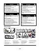
DANGER WARNING POTENTIAL HAZARD • There may be buried power, gas, and/or telephone lines in the work area. POTENTIAL HAZARD • When going up or down hill, the machine could overturn if the heavy end is toward the downhill side. WHAT CAN HAPPEN • Electric shock, death, or explosion may occur. WHAT CAN HAPPEN • Someone may be pinned or seriously injured by the machine if it overturns. HOW TO AVOID THE HAZARD • Have the property or work area marked for buried lines and do not dig in marked areas.
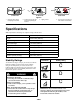
1 3 2 # 100–4134 # 100–4135 # 100–4137 Figure 2 1. Secure the boom before transporting the backhoe 2. Install and secure the side bars before operating the backhoe 3. Tipping hazard 4. Do not move the traction unit while seated on the backhoe Specifications Note: Specifications and design are subject to change without notice. Width 34.5 inches (87.6 cm) Length 112.
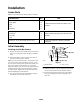
Installation Loose Parts Note: Use the chart below to identify parts for assembly. DESCRIPTION QTY. Side bar bracket 2 Back-plate 2 Bolt 6 Nut 6 Side bar 2 Long tilt cylinder pin 1 Cotter pin 2 Linch pin 2 Link 2 Bucket, 9, 12, or 16 inch (23, 30, or 41 cm) 1 USE Install the side bar brackets and attach to the backhoe. Replace the tilt cylinder pin and connect to the backhoe. Install on the backhoe. Must be purchased separately.
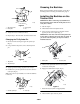
Greasing the Backhoe 3 Before using the backhoe for the first time, grease all of the fittings; refer to Greasing and Lubrication, page 13. 2 Installing the Backhoe on the Traction Unit 4 1 IMPORTANT: Before connecting any attachments to the traction unit, ensure that the mount plates are free of any dirt or debris. m–4586 Figure 4 1. Side bar bracket 2. Back-plate 1. Start the engine. 3. Carriage bolt 4. Nut 2. Tilt the attachment mount plate forward. 3.
. Stop the engine. Note: You may need to move the attachment tilt lever to line up the holes in the links with the pins. 8. Move the auxiliary hydraulic lever forward, backward, and back to the neutral position to relieve hydraulic pressure at the hydraulic couplers. 4 4 IMPORTANT: Ensure that all foreign matter is cleaned from hydraulic connections before making connections. 1 2 9. Remove protective covers from hydraulic couplers on the traction unit.
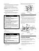
4. Align the pin holes in the bucket with the mounting holes in the dipperstick (Fig. 11). 5. Secure the bucket with the pins, bolts, and nuts removed previously (Fig. 11). 1 4 4 2 1 2 3 3 m–4589 Figure 12 Figure 11 1. Dipperstick 2. Bucket pin m–4547 1. Seat 2. Knobs 3. Bolt 4. Nut 3. Pin and hairpin cotter 5. When you have the proper height, install the pin and hairpin cotter to secure the seat.
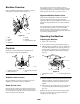
Operation 6. Secure the links and two linch pins for storage on the pins on the backhoe and the other two linch pins on the traction unit tilt cylinder pin. Note: Always use the traction unit to lift and move the attachment. 7. Tilt the backhoe forward slowly until the storage supports on the backhoe receiver plate and the bucket contact the ground.
Backhoe Overview You can also move the boom control lever into an intermediate position (i.e., forward and left, forward and right, rearward and left, or rearward and right) to swing the boom at the same time as you raise or lower it. Figure 14 illustrates the backhoe. Familiarize yourself with all of the components listed in Figure 14. 2 Dipperstick/Bucket Control Lever 3 4 Move the dipperstick/bucket control lever forward to extend the dipperstick and rearward to retract the dipperstick.
A 1 2 m–4548 Figure 17 1. Pin B 2. Linch pin C 2 1 m–4550 Figure 18 1. Pin m–4554/4555/4556 2. Linch pin Figure 20 To empty the bucket you swing it to the left or right and extend the dipperstick and uncurl bucket, dumping the load (Fig. 21). A 1 B m–4557/4558 2m–4549 Figure 19 1. Pin 2.
• Do not dig too close to the backhoe body or stabilizers. The backhoe could undercut the stabilizers or traction unit causing the machine to fall into the hole. CAUTION WARNING POTENTIAL HAZARD • If you do not secure the boom, it could swing or lower during transport. WHAT CAN HAPPEN • The traction unit could become unstable causing loss of control and you or bystanders could be injured. POTENTIAL HAZARD • If you dig too close to the backhoe, the backhoe could fall into the hole.
Service Interval Chart Service Operation 8 Storage Hours Service Grease fittings X Chipped surfaces–paint X X Greasing and Lubrication Service Interval/Specification Grease all fittings every 8 operating hours (Fig. 23). Note that in most cases the grease fittings are located in the center of every pivot pin. Grease all fittings immediately after every washing. m–4587 Grease Type: General-purpose grease How to Grease 1. Stop the engine and remove the key. 2. Clean the grease fittings with a rag. 3.
m–4589 The two valves that control the left and right swing of the boom are located inside of the controls access panel (Fig. 26). To access these valves, remove six locknuts and the panel. Adjust both valves equally. Replace the access panel when finished. 1 4 4 5 1 2 3 Figure 24 4. Nut 5. Second set of holes 1. Dipperstick 2. Upper bucket pin 3. Bolt m–4587 Figure 26 1.
Troubleshooting PROBLEM Backhoe does not operate Backhoe is operating slowly Backhoe fails to hold up p a load (all ( loads will ill normally normall settle down do n over a long period of time) Hydraulic y oil leakage g POSSIBLE CAUSES CORRECTIVE ACTION 1. Hydraulic coupler not completely connected 1. Check and tighten all couplers. 2. Auxiliary hydraulics valve on the traction unit is not fully engaged. 2. Engage the valve. 3. Transport pins were not removed. 3. Remove the pins. 4.
PROBLEM POSSIBLE CAUSES CORRECTIVE ACTION Swing cylinder malfunctioning 1. Damaged cylinders, swing restrictors, or cross-over relief valve 1. Contact your Authorized Toro Dealer. Control valve sticking g or working g hard 1. Dirty hydraulic oil 1. Change the hydraulic oil. 2. Damaged or dirty valve 2. Contact your Authorized Toro Dealer. 3. Damaged cylinder 3. Contact your Authorized Toro Dealer. 1. Hydraulic fluid level is low. 1. Fill the traction unit hydraulic tank. 2.