
Operator's Manual


10
Backhoe
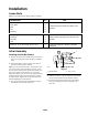
Overview
Figure
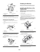
14 illustrates the backhoe. Familiarize yourself
with all of the components listed in Figure 14.
m–4587
5
4
3
1
6
2
7
Figure
14
1. Seat
2. Controls
3. Boom
4. Dipperstick
5. Bucket
6. Stabilizer
7. Speed
adjustment valve
Controls
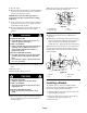
Familiarize
yourself with all of the controls listed in
Figure 15 before you operate the backhoe.
m–4546
3
2
1
Figure
15
1. Stabilizer
control levers
2.
Boom control lever
3.
Dipperstick/bucket control
lever
Stabilizer Control Levers
Move
the stabilizer control levers forward to lower the
stabilizers and rearward to raise the stabilizers.
Boom Control Lever
Move
the boom control lever forward to lower the boom
and rearward to raise the boom. Move the boom control
lever to the right to swing the boom to the right and move
it left to swing the boom to the left.
Y
ou can also move the boom control lever into an
intermediate position (i.e., forward and left, forward and
right, rearward and left, or rearward and right) to swing
the boom at the same time as you raise or lower it.
Dipperstick/Bucket Control Lever
Move
the dipperstick/bucket control lever forward to
extend the dipperstick and rearward to retract the
dipperstick. Move the dipperstick/bucket control lever to
the right to dump the bucket and move it left to load the
bucket.
Y
ou can also move the dipperstick/bucket control lever
into an intermediate position (i.e., forward and left,
forward and right, rearward and left, or rearward and
right) to extend or retract the dipperstick at the same time
as you load or dump the bucket.
Operating
the Backhoe
Preparing the Backhoe
1. Drive
to the work location.
2.
If your traction unit has a parking brake, engage it.
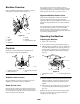
3.
Pull the auxiliary hydraulics lever to the operator grip
and install the hydraulics lever clamp by pushing it
over the hand grip and sliding it right so that the pin
through the clamp slides under the right hand grip
(Fig. 16).
1
2
3
m–4641
Figure
16
1. Hydraulics
lever clamp
2. Pin
3.
Auxiliary hydraulics lever
4. Push
the stabilizer control levers forward to lower both
stabilizers until they touch the ground and the front
wheels of the traction unit come of
f of the ground
slightly.
5.
Remove the two pins locking the boom in place (Figs.
17 and 18) and place them in the storage positions
(Fig. 19).
Note:
One pin prevents the boom from swinging side to
side (Fig. 17) and the other prevents the boom from
moving up and down (Fig. 18).