
Operator's Manual


6
m–4586
4
3
2
1
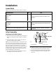
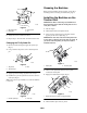
Figure
4
1. Side
bar bracket
2. Back-plate
3.
Carriage bolt
4. Nut
6. Torque
the nuts to 75 ft-lbs (102 N·m).
7.
Repeat steps 3–6 for the other side of the traction unit.
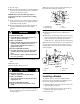
Changing the Tilt Cylinder Pin
1. Remove
the bolt securing the upper tilt cylinder pin
(Fig. 5).
2.
Using a hammer and punch, remove the tilt cylinder
pin.
m–4562
2
1
3
Figure
5
1. Tilt
cylinder
2. T
ilt cylinder pin
3. Bolt
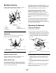
3. Apply
a generous coating of grease to the new pin.
4.
Install the new pin into position and secure it with two
cotter pins (Fig. 6).
Note:
Leave the new pin installed, even when the backhoe
is removed.
m–4563
1
2
Figure
6
1. New
tilt cylinder pin
2.
Cotter pin
Greasing
the Backhoe
Before
using the backhoe for the first time, grease all of
the fittings; refer to Greasing and Lubrication, page 13.
Installing
the Backhoe on the
T
raction Unit
IMPORTANT:
Befor
e connecting any attachments to
the traction unit, ensur
e that the mount plates ar
e fr
ee
of any dirt or debris.
1.
Start the engine.
2. T
ilt the attachment mount plate forward.
3.
Drive forward, positioning the mount plate into the
upper lip of the receiver plate (Fig. 7).
IMPORTANT
: Y
ou must center the mount plate in the
r
eceiver plate so that the gaps on the sides are equal. If
you do not center the plates, you may not be able to
install the side bars.
m–4055
1
2
Figure
7
1. Mount
plate
2.
Receiver plate
4. Tilt
the mount plate back until the receiver plate
contacts the mount plate
5.
Engage the attachment lock pins (Fig. 8).
m–4056
1
Figure
8
1. Attachment
lock pins (shown in engaged position)
6. Tilt
the backhoe part of the way back.