Form No. 3353-815 Rev A Trencher for TX 413 Compact Utility Loaders Model No. 22465—240000001 and Up Operator’s Manual Register your product at www.Toro.
Contents Introduction . . . . . . . . . . . . . . . . . . . . . . . . . . . . . . . . Safety . . . . . . . . . . . . . . . . . . . . . . . . . . . . . . . . . . . . . Safety Decals . . . . . . . . . . . . . . . . . . . . . . . . . . . . Specifications . . . . . . . . . . . . . . . . . . . . . . . . . . . . . . . Stability Ratings . . . . . . . . . . . . . . . . . . . . . . . . . . Operation . . . . . . . . . . . . . . . . . . . . . . . . . . . . . . . . . . Checking the Bearing Case Lube Level . . . . . . .
Safety Warning To ensure maximum safety and best performance, and to gain knowledge of the product, it is essential that you and any other operator of the product read and understand the contents of this manual before the engine is ever started. The loader arms may lower when in the raised position after stopping the engine, crushing anyone under them. Lower the loader arms before stopping the engine. This is the safety alert symbol. It is used to alert you to potential personal injury hazards.
Safety Decals 99-9952 1. Cutting hazard, chain and auger—stay away from moving parts and keep bystanders away. 2. Warning—stop the engine and remove the key before performing maintenance or repairs. 3. Explosion and/or electric shock hazard—do not dig in areas with buried gas or power lines.
8. When finished, raise the trencher and boom out of the trench by tilting the attachment rearward, then stop the trencher by shifting the auxiliary hydraulics lever into neutral. Important Always use the traction unit to lift and move the attachment. Checking the Bearing Case Lube Level Tips for Trenching Before operating the trencher, ensure that the bearing case is filled with gear lube. • Clean the area of trash, branches, and rocks before trenching to prevent equipment damage. 1.
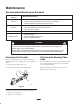
Maintenance Recommended Maintenance Schedule Maintenance Service Interval Maintenance Procedure 8 hours • Grease all fittings. • Check the teeth and replace any that are worn or damaged. • Tighten the bolt and nut securing the spoils auger. 25 hours • Adjust the digging chain tension. • Check the condition of the bearing case lube. • Check the boom for wear. 200 hours • Change the bearing case lube. • Grease all fittings. • Adjust the digging chain tension. • Paint any chipped surfaces.
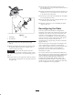
Adjusting the Digging Chain Tension Checking the Bearing Case Lube 1. Clean the area around the gear case fill hole plug (Fig. 3). Adjust the digging chain every 25 operating hours. With the trencher parallel to the ground, ensure that there are 1-1/2 to 2-1/2 inches (4 to 6 cm) between the bottom of the boom and the top of the bottom chain span. If not, adjust the chain using the following procedure: 1 Important Do not overtighten the chain. Excess chain tension may damage drive components. 1.
13. Thread the adjustment bolt into the boom and turn it in until there is 1-1/2 to 2-1/2 inches (4 to 6 cm) of slack in the chain on the bottom span. 2. Loosen the 2 bolts and nuts securing the boom to the trencher arm (Fig. 4). 3. Loosen the jam nut securing the adjustment bolt (Fig. 4). 14. Thread the jam nut down the adjusting bolt and tighten it securely against the boom. 4. Turn the adjustment bolt in or out as needed to achieve the desired tension. 15.
15. Set the upper span of the chain into place on the trencher boom, then wrap the chain around the roller at the end of the boom. 16. Thread the adjustment bolt into the boom and turn it in until there is 1-1/2 to 2-1/2 inches (4 to 6 cm) of slack in the chain on the bottom span. 17. Thread the jam nut down the adjusting bolt and tighten it securely against the boom. 2 18. Torque the 2 bolts and nuts securing the boom to 135 to 165 ft-lb. (183 to 223 N⋅m). 1 19.
2 4 5 8 2 6 7 1 8 1 6 3 10 7 9 11 12 m–4407, 4408, 4409, 4449 Figure 6 1. 2. 3. 4. 5. Chain link Left, cupped tooth Right, cupped tooth Short tube Long tube 6. Spacer for 6 in. (15 cm), double cupped configuration. 7. Bolt 8. Nut 9. Left triangular rock tooth 10. Right triangular rock tooth 11. Spacer for 6 in. (15 cm), triangular rock tooth configuration 12. Washer (for use with triangular rock teeth only) Setting the Spoils Auger Width 1.
Storage 3 1. Before long term storage, brush the dirt from the attachment. 1 2. Check the condition of the digging chain. Adjust and lubricate the chain. Replace any worn or damaged teeth. 2 3. Check and tighten all bolts, nuts, and screws. Repair or replace any part that is damaged or worn. 4. Ensure that all hydraulic couplers are connected together to prevent contamination of the hydraulic system. 5. Paint all scratched or bare metal surfaces with paint available from an Authorized Service Dealer.
Typical Soil, 4 in.
Typical Soil, 6 in. (15 cm) Trench Tooth Position and Configuration Tooth Position and Configuration Tooth Position and Configuration 1 9 17 2 10 18 3 11 19 4 12 20 5 13 21 6 14 22 7 15 23 6 in. (15 cm) double cupped 6 in. (15 cm) double cupped 16 24 6 in.
Sand and Loose Soil, 4 in.
Sand and Loose Soil, 6 in. (15 cm) Trench Tooth Position and Configuration Tooth Position and Configuration Tooth Position and Configuration 1 9 17 2 10 18 3 11 19 4 12 20 6 in. (15 cm) double cupped 6 in. (15 cm) double cupped 5 13 21 6 14 22 7 15 23 8 16 24 6 in. (15 cm) double cupped 6 in. (15 cm) double cupped 6 in. (15 cm) double cupped 6 in.
Hard or Rocky Ground, 4 in.
Hard or Rocky Ground, 6 in.
Rock, 4 in.
Rock, 6 in.
Troubleshooting PROBLEM The chain does not turn. The auger g does not dig g fast enough. h The chain turns in the wrong direction. The bearing case lube is contaminated. POSSIBLE CAUSES CORRECTIVE ACTION 1. The hydraulic coupler is not completely connected. 1. Check and tighten the hydraulic coupler. 2. The hydraulic coupler is damaged. 2. Check and replace couplers, if necessary. 3. There is an obstruction in a hydraulic hose. 3. Find and remove the obstruction. 4.