Form No. 3429-943 Rev B Auger Drive TXL 2000 Tool Carrier Model No. 22532—Serial No. 318000001 and Up Register at www.Toro.com.
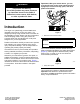
Important: With your mobile device, you can scan the QR code on the serial number decal (if equipped) to access warranty, parts, and other product information. WARNING CALIFORNIA Proposition 65 Warning Use of this product may cause exposure to chemicals known to the State of California to cause cancer, birth defects, or other reproductive harm. Introduction The auger is a hydraulically powered attachment intended to be used on a Toro tool carrier.
Contents Safety Safety ....................................................................... 3 General Safety ................................................... 3 Slope Safety ....................................................... 4 Auger Safety....................................................... 4 Maintenance and Storage Safety........................ 4 Safety and Instructional Decals .......................... 5 Product Overview .....................................................
Slope Safety Auger Safety • Operate the machine up and down slopes with • Keep your hands, feet, and any other part of your the heavy end of the machine uphill. Weight distribution changes with attachments. This attachment makes the front of machine the heavy end. body or clothing away from moving auger or other parts. • Keep your hands and fingers away from the cradle arms.
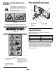
Safety and Instructional Decals Product Overview Safety decals and instructions are easily visible to the operator and are located near any area of potential danger. Replace any decal that is damaged or missing. g266844 decal125-6128 Figure 3 125-6128 1. High pressure fluid hazard, injection into the body—read the Operator’s Manual before performing maintenance. 1. Mounting plate 4. Drive head 2. Motor 3. Cradle arms 5.
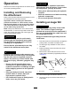
Operation CAUTION Hydraulic couplers, hydraulic lines/valves, and hydraulic fluid may be hot. If you contact hot components, you may be burned. Determine the left and right sides of the machine from the normal operating position. • Wear gloves when operating the hydraulic couplers. Installing and Removing the Attachment • Allow the machine to cool before touching hydraulic components. Refer to the Operator’s Manual for the traction unit for the installation and removal procedure.
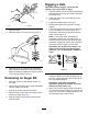
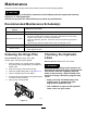
Digging a Hole Important: Before digging, ensure that the ground is free of any trash or debris. g266891 Figure 5 1. Pin 2. Lockpin 7. Start the engine. 8. Raise the auger free of the ground (Figure 6). 1. Raise the loader arms and rotate the attachment plate forward so that the drive head is free from the cradle arms. 2. Lower the auger to the soil at the site of the proposed hole. 3. Toggle the throttle switch to HIGH IDLE. 4. Engage the forward flow hydraulics to begin digging. 5.
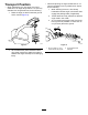
Transport Position • When transporting an auger smaller than 51 cm (20 inch) diameter over long distances or slopes, do the following: • When transporting any size auger over short distances or an auger larger than 51 cm (20 inch) diameter over longer distances, do the following: 1. Raise the auger so that it clears the ground and is vertical (Figure 8). 1. While lowering the arms, drive slowly backwards until the auger is horizontal, then engage the parking brake (if applicable). 2.
Maintenance Determine the left and right sides of the machine from the normal operating position. CAUTION If you leave the key in the switch, someone could accidently start the engine and seriously injure you or other bystanders. Remove the key from the switch before you perform any maintenance. Recommended Maintenance Schedule(s) Maintenance Service Interval Maintenance Procedure After the first 50 hours • Change the planetary gearcase oil.
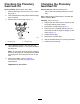
Checking the Planetary Gearcase Oil Changing the Planetary Gearcase Oil Service Interval: Before each use or daily Service Interval: After the first 50 hours 1. Remove the auger; refer to Removing an Auger Bit (page 7) Every 1,000 hours/Yearly (whichever comes first) 2. Tilt the attachment mount plate so that the auger drive is vertical. Type: 80W-90 gear oil that meets or exceeds API service category GL-5 3. Remove the oil-check plug (Figure 11). Capacity: 0.
Storage 1. Before long-term storage, wash the attachment with mild detergent and water to remove dirt and grime. 2. Check and tighten all bolts, nuts, and screws. Repair or replace any damaged or worn part. 3. Ensure that all hydraulic couplers are connected together to prevent contamination of the hydraulic system. 4. Paint all scratched or bare metal surfaces. Note: Paint is available from your Authorized Service Dealer. 5. Store the attachment in a clean, dry garage or storage area.
Troubleshooting Problem The drive head does not operate. Possible Cause Corrective Action 1. Hydraulic coupler not completely connected. 1. Check and tighten all couplers. 2. A hydraulic coupler needs to be replaced. 3. There is an obstruction in a hydraulic hose. 4. A hydraulic hose is kinked. 5. The gearbox is contaminated. 2. Check the couplers and replace any that are worn or damaged. 3. Find and remove the obstruction. 12 4. Replace the kinked hose. 5. Refer to your Authorized Service Dealer.
Notes:
Notes:
Notes:
California Proposition 65 Warning Information What is this warning? You may see a product for sale that has a warning label like the following: WARNING: Cancer and Reproductive Harm—www.p65Warnings.ca.gov. What is Prop 65? Prop 65 applies to any company operating in California, selling products in California, or manufacturing products that may be sold in or brought into California.