Form No. 3438-837 Rev D Snow Thrower TXL 2000 and Compact Tool Carriers Model No. 22583—Serial No. 320000001 and Up Model No. 22585—Serial No. 320000001 and Up Register at www.Toro.com.
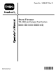
WARNING CALIFORNIA Proposition 65 Warning Use of this product may cause exposure to chemicals known to the State of California to cause cancer, birth defects, or other reproductive harm. Introduction g327524 Figure 1 Model 22585 shown This snow thrower is intended to be used on a Toro tool carrier or compact tool carrier. It is designed primarily for removing snow from paved surfaces, such as driveways and sidewalks, and other surfaces for traffic on residential or commercial properties.
Contents Safety Safety ....................................................................... 3 General Safety ................................................... 3 Slope Safety ....................................................... 3 Snow Thrower Safety ......................................... 4 Maintenance and Storage Safety........................ 4 Safety and Instructional Decals .......................... 5 Setup ........................................................................
• Slopes are a major factor related to loss of control • Let the engine and machine adjust to outdoor and tip-over accidents, which can result in severe injury or death. Operating the machine on any slope or uneven terrain requires extra caution. temperatures before starting to clear the snow. • Never direct the discharge toward people or areas where property damage can occur. • Establish your own procedures and rules for • Exercise caution to avoid slipping or falling, operating on slopes.
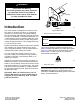
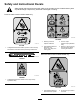
Safety and Instructional Decals Safety decals and instructions are easily visible to the operator and are located near any area of potential danger. Replace any decal that is damaged or missing. Decal 93-7309 is used on Model 22583 only. decal139-8895 139-8895 1. Warning—read the Operator’s Manual. 3. Thrown object hazard—keep bystanders away. 2. Cutting/dismemberment hazard of foot, auger—stay away from moving parts. 4. Warning—remove the key from the ignition before servicing the machine.
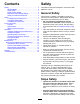
decal144-2519 144-2519 1. Rotate the deflector left. 2. Rotate the deflector right. 3. Raise the deflector chute 4.
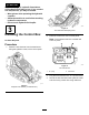
Setup Loose Parts Use the chart below to verify that all parts have been shipped. Procedure 1 2 3 Description Use Qty. Accessory port kit (sold separately) 1 Install the accessory port. No parts required – Install the attachment. No parts required – Install the control box. WARNING 1 If you do not fully seat the quick-attach pins through the attachment mount plate, the attachment could fall off the machine, crushing you or bystanders.
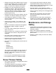
CAUTION Hydraulic couplers, hydraulic lines/valves, and hydraulic fluid may be hot. If you contact hot components, you may be burned. • Wear gloves when operating the hydraulic couplers. • Allow the machine to cool before touching hydraulic components. • Do not touch hydraulic fluid spills. g328045 3 Figure 4 TXL 2000 with telescoping arms Installing the Control Box 2. Place the control box on the control panel. Note: The magnets under the controller will hold it in place.
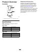
Attachments/Accessories Product Overview A selection of Toro approved attachments and accessories is available for use with the machine to enhance and expand its capabilities. Contact your Authorized Service Dealer or authorized Toro distributor or go to www.Toro.com for a list of all approved attachments and accessories. Controls To ensure optimum performance and continued safety certification of the machine, use only genuine Toro replacement parts and accessories.
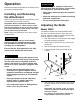
Operation CAUTION Hydraulic couplers, hydraulic lines/valves, and hydraulic fluid may be hot. If you contact hot components, you may be burned. Determine the left and right sides of the machine from the normal operating position. • Wear gloves when operating the hydraulic couplers. Installing and Removing the Attachment • Allow the machine to cool before touching hydraulic components. Refer to the Operator’s Manual for the traction unit for the installation and removal procedure.
Note: You can also place a sturdy object of the 5. desired scraper height under the scraper and lower the scraper onto it. 6. Shut off the engine and remove the key. 7. Position the skids evenly on both sides so that the bottom edges contact or are parallel with the surface. Important: For cracked, rough, or uneven surfaces, position the skids lower. For smooth, paved surfaces, position the skids higher so that the scraper blade is closer to the surface.
Clearing a Clogged Snow Thrower Operating Tips • Engage and disengage the snow thrower auger at low throttle. • Use the chute direction control to rotate the chute WARNING 180° side to side . If the auger/impeller is running but there is no snow coming out of the discharge chute, the discharge chute may be clogged. • When clearing snow when you can discharge snow on both sides of the path, clear the snow from the center of the path and then clear outwards.
Maintenance Determine the left and right sides of the machine from the normal operating position. CAUTION If you leave the key in the switch, someone could accidently start the engine and seriously injure you or other bystanders. Remove the key from the switch before you perform any maintenance. Recommended Maintenance Schedule(s) Maintenance Service Interval Before each use or daily Every 100 hours Before storage Yearly or before storage Maintenance Procedure • Grease the snow thrower.
Checking and Replacing the Skids Replacing the Scraper Blade Service Interval: Every 100 hours Service Interval: Every 100 hours—Check the condition of the scraper blade. Yearly or before storage Yearly or before storage—Check the condition of the scraper blade. Check the skids for wear. Rotate the skids or replace them when worn. The scraper blade contacts the ground to prevent damage to the snow thrower housing. Periodically inspect the scraper blade for wear.
Checking the Hydraulic Lines Storage 1. Before long term storage, wash the attachment with mild detergent and water to remove dirt and grime. 2. Check the condition of the scraper blade. 3. Check and tighten all bolts, nuts, and screws. Repair or replace any damaged or worn parts. 4. Paint all scratched or bare metal surfaces. Paint is available from your Authorized Service Dealer. 5. Store the attachment in a clean, dry garage or storage area. Cover it to protect it and keep it clean.
Troubleshooting Problem The snow thrower does not operate. The chute does not rotate or the deflector does not raise or lower. Possible Cause Corrective Action 1. A hydraulic coupler is not completely connected 1. Check and tighten all couplers. 2. A hydraulic coupler is damaged. 2. Check the couplers and replace any that are damaged. 3. Find and remove the obstruction. 3. There is an obstruction in a hydraulic hose. 4. A hydraulic hose is kinked. 5.
Notes:
Notes:
Notes:
California Proposition 65 Warning Information What is this warning? You may see a product for sale that has a warning label like the following: WARNING: Cancer and Reproductive Harm—www.p65Warnings.ca.gov. What is Prop 65? Prop 65 applies to any company operating in California, selling products in California, or manufacturing products that may be sold in or brought into California.