Operator’s Manual Form No. 3366-779 Rev B Register your product at www.Toro.com Brush Chipper Model No. 22604-Serial No. 310000001 and Up Model No. 22604THD-Serial No.
This product complies with the US National Highway Traffic Safety Administration (NHTSA) regulations for street legal trailers. WARNING The engine exhaust from this product contains chemicals known to the State of California to cause cancer, birth defects, or other reproductive harm. This Manual identifies potential hazards and has safety messages identified by the safety alert symbol, (Figure 1) which signals a hazard that may cause serious injury or death if you do not follow the recommended precautions.
group of vehicles*, it may order a recall and remedy campaign. However, NHTSA cannot become involved in individual problems between you, your dealer, or The Toro Company. To contact NHTSA, you may call the Vehicle Safety Hotline toll-free at 1–888–327–4236 (TTY: 1–800–424–9153); go to http://www.safercar.gov ; or write to: Administrator, NHTSA, 400 Seventh Street, SW., Washington, DC 20590. You can also obtain other information about motor vehicle safety from http://www.safercar.gov.
• Never leave this machine unattended with the engine running. • Never operate machine while under the influence of alcohol, drugs, or medication. • Never allow anyone to operate this machine without proper instruction. • Always operate this machine with all safety equipment in place and working. • Do not change the engine governor setting or over speed the engine.
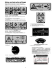
Safety and Instructional Decals Safety decals and instructions are easily visible to the operator and are located near any area of potential danger. Replace any decal that is damaged or lost. 117-4979 1. Belt entanglement hazard – keep hands away from moving parts. 119-4698 1. Warning – read the Operator’s Manual. 2. Warning – do not operate the brush chipper unless you have been trained. 3. Thrown object hazard – wear safety glasses. 4.
Product Overview 5 4 8 13 11 9 1 3 12 2 7 6 10 14 Figure 3 1. Coupler 2. Safety Chains 3. Jack stand 4. Chute locking pin 5. Deflector locking knob 6. Battery box 7. Flywheel bearing 8. Hopper 9. Key switch 10. Fuel cap 11. Air filter 12. Throttle 13. Choke 14. Fuel filter Controls Hopper Latch The hopper, mounted on the side of the machine, swings down for machine operation. The revolving blades mounted on a flywheel behind the hopper turns branches fed into the hopper into “chips”.
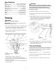
Specifications Engine ......................................... 25 HP (18.6 kW) Kohler Hopper Opening......................... 6 inch (15 cm) maximum Wheels & Tires ............................... High-Speed, 4.80 x 12 Hitch Coupler ................................................2 inch (5 cm) Safety Chains ........................................................ Standard Jack Stand with two caster wheels ................. 4.10/3.50 x 4 Fuel Tank Capacity .................................. 5.5 Gal. (20.
• If a gasoline dispenser nozzle must be used, keep the nozzle in contact with the rim of the fuel tank or container opening at all times until fueling is complete. Operation Before You Start Do not use methanol, gasoline containing methanol, or gasohol containing more than 10% ethanol because the fuel system could be damaged. Do not mix oil with gasoline. Review all the machine’s safety decals.
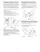
Checking the Engine Oil Level Changing the Chute Position The best time to check the engine oil is when the engine is cool before it has been started for the day. If it has already been run, allow the oil to drain back down to the sump for at least 10 minutes before checking. If the oil level is at or below the “L” mark on the dipstick, add oil to bring the oil level to the “H” mark. Do not overfill. If the oil level is between the “H” and “L” marks, no oil addition is required.
Starting and Stopping the Engine Stopping the Engine Starting the Engine 1. Move the choke lever left to the ON position if you are starting a cold engine (Figure 12). A warm or hot engine may not require choking. 2. Move the throttle lever 1/3 way to the FAST position (Figure 12). 1. Move the throttle lever to the SLOW position. If the engine has been working hard or is hot, let it run for a minute before turning off. This helps to cool the engine before stopping.
Figure 15 • Overloading the hopper will cause the rotor speed to decrease. If you hear the engine RPM decreasing, stop feeding material into the hopper until the engine has returned to full speed (Figure 15). • If you jam the machine and do not stop the engine, it can damage the machine (Figure 16). For this reason, it is important that you immediately stop the engine if the machine becomes jammed, wait five minutes to make certain the flywheel and all moving parts have come to a complete stop and cool.
Servicing the Air Cleaner Foam pre-filter: Clean every 25 hours. Paper Filter: Check every 25 operating hours. Replace the air filter every 100 hour. 4. Squeeze the pre-filter to distribute the oil. 5. Lightly tap the paper filter on a flat surface to remove dust and dirt (Figure 19). Note: Service the air cleaner more frequently if operating conditions are extremely dusty or sandy. Removing the Filters 1. Clean around the air cleaner to prevent dirt from getting into the engine and causing damage. 2.
Changing the Oil and Filter Service Interval: After the first 50 hours Every 100 hours 1. Start the engine and let it run five minutes. This warms the oil so it drains better. 2. Park the traction unit so that the drain side is slightly lower than the opposite side to ensure that the oil drains completely. 3. Place one end of a hose on the drain valve and the other end in a pan (Figure 21). 4. Open the drain valve by turning it counterclockwise, pulling out as you turn it (Figure 21). 10.
Checking the spark Plugs Service Interval: Every 200 Hours Charging the Battery 1. Look at the center of both spark plugs (Figure 24). If you see light brown or gray on the insulator, the engine is operating properly. A black coating on the insulator usually means the air cleaner is dirty. Important: Never clean the spark plugs. Always replace the spark plugs when they have a black coating, worn electrodes, an oily film, or cracks. 2. Check the gap between the center and side electrodes (Figure 24). 3.
9. Charge the battery for 10 to 15 minutes at 25 to 30 amps or 30 minutes at 4 to 6 amps (Figure 26). Do not overcharge the battery. 10. When the battery is fully charged, unplug the charger from the electrical outlet, then disconnect the charger leads from the battery posts (Figure 26). 11. Install the battery cover. 3. Loosen four (4) engine plate mounting bolts and four (4) bolts securing the rear of the belt guard to the engine. 4.
1. Remove the bolt and washer securing the flywheel housing cover, swing it forward to expose the flywheel. 2. Rotate the flywheel using a stick until the bolts and lock nuts attaching the cutter blades to the flywheel are accessible (Figure 31). 2. Cutter block Lubricate the Wheel Bearings Service Interval: Every 500 hours. Lubricate the wheel bearings with several pumps of No. 2 General Purpose lithium base grease (Figure 33). 3-2 1 Figure 32 1. Blade 3-3 3-1 3-1 1 2 Figure 31 Figure 33 1.
Figure 35 is an example of tire wear caused by under inflation. Storage For storage over 30 days, prepare the unit as follows: 1. Remove dirt and grime from the external parts of the entire unit, especially the engine. Clean dirt and wood chips from the outside of the engine cylinder head fins and blower housing. 2. Add a petroleum based stabilizer/conditioner to fuel in the tank. Follow mixing instructions from stabilizer manufacturer. (1 oz per US gallon).
Troubleshooting Problem Cause Remedy The engine will not start. 1. The engine switch is in the Off position. 2. The choke is open. 1. Turn the engine switch to the ON position. The engine runs rough. Chipping action seems slow or flywheel stalling. Flywheel does not turn. Drive belt worn, burned, or jumps off of pulley. The machine has excessive vibration. 3. The fuel tank is empty 4. Throttle is not in correct position. 5. The spark plug(s) are fouled, wire is loose or disconnected. 1.
Notes: 19
Toro Compact Utility Equipment Warranty A One-Year Limited Warranty Conditions and Products Covered The Toro® Company and its affiliate, Toro Warranty Company, pursuant to an agreement between them, jointly warrant your Toro Compact Utility Equipment (“Product”) to be free from defects in materials or workmanship.