Form No. 3373-142 Rev B BC-25 Brush Chipper Model No. 22614—Serial No. 311000001 and Up Model No. 22614G—Serial No. 311000001 and Up Model No. 32614—Serial No. 312000001 and Up G017901 Register at www.Toro.com.
You may contact Toro directly at www.Toro.com for product and accessory information, help finding a dealer, or to register your product. WARNING CALIFORNIA Proposition 65 Warning The engine exhaust from this product contains chemicals known to the State of California to cause cancer, birth defects, or other reproductive harm.
Contents Safety Introduction .................................................................. 2 Safety ........................................................................... 3 Safe Operating Practices........................................... 3 Safety and Instructional Decals ................................. 6 Product Overview .......................................................... 8 Controls ................................................................ 8 Specifications ....................
Towing protection. Long hair, loose clothing or jewelry may get tangled in moving parts. Wear tight fitting gloves without drawstrings or loose cuffs. Check with your local county or state safety towing regulations, in addition to meeting Department of Transportation (DOT) Safety Towing Regulations, before towing the machine.
• Ensure that the area is clear of other people before – Inspect the coupler, ball and hitch. operating the machine. Stop the machine if anyone enters the area. – Ensure that all lights are functioning properly. – Ensure that the tires are properly inflated as recommended. • Never leave a running machine unattended. Always stop the engine and verify the chipper flywheel has stopped rotating. – Ensure that the lug nuts are tight and torqued properly.
Safety and Instructional Decals Safety decals and instructions are easily visible to the operator and are located near any area of potential danger. Replace any decal that is damaged or lost. 117–2718 119-4698 1. Warning—read the Operator's Manual. 2. Warning—read the Operator's Manual, do not operate this machine unless you are trained. 3. Thrown object hazard, face—wear eye protection. 4. Thrown object hazard—keep bystanders a safe distance from the machine. 5.
117–4979 1. Rotating belt — Keep guard in place 120-3738 1. When chipping branches with widths of 4 to 6 inches, cut the branches to lengths of 36 inches or less to prevent clogging of the chipper.
Product Overview 4 5 6 9 7 8 10 11 12 3 13 14 15 16 2 1 18 17 G017902 Figure 3 1. Safety chains 10. Choke 2. Coupler 11. Throttle 3. Jack stand 4. Deflector locking knob 12. Air filter 13. Key switch 5. Deflector 14. Fuel level gauge 6. Chute locking pin 15. Fuel cap 7. Chute locking knob 16. Fuel filter 8. Hopper 17. Battery 9. Discharge chute 18. Flywheel bearing Controls Become familiar with all the controls before you start the engine and operate the machine.
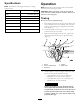
Specifications Operation Note: Specifications and design are subject to change without notice. Hopper Opening Length 6 inches (15 cm) maximum diameter 35 inches (89 cm) Height 81 inches (206 cm) Weight 1056 lbs (478 Kg) Engine Kohler 725cc, V-Twin, gas Fuel Tank Capacity Important: Before operating, check the fuel and oil level, and remove debris from the machine. Ensure that the area is clear of people.
• Ensure that everyone, including children and animals, 5. Install the locking pin to secure the lever (Figure 5). maintain a distance of at least 50 feet (15 m) from the machine. Debris can be thrown out and injure people and animals. 6. Cross or “X” the safety chains and attach them to the holes on the hitch. 7. Plug tail light wire harness connector to the tow vehicle connector.
Adding Fuel Using Stabilizer/Conditioner Use unleaded gasoline (87 pump octane minimum). Leaded, regular gasoline may be used if unleaded is not available. Use a fuel stabilizer/conditioner in the machine to provide the following benefits: • Keeps gasoline fresh during storage of 90 days or less. For longer storage it is recommended that the fuel tank be drained. • Cleans the engine while it runs. • Eliminates gum-like varnish buildup in the fuel system, which causes hard starting.
Changing the Chute Position The discharge chute on this machine can be rotated to use in various positions. Rotate to the side, away from the hopper when using the machine. 1. To rotate, loosen the clamp knob, then press the spring-loaded button on the locking pin handle in and pull the locking pin from the chute plate (Figure 10). G016607 Figure 8 1. Hour meter Checking the Engine Oil Level Service Interval: Before each use or daily 1. Place the machine on a flat level surface, and stop the engine.
6. When ready to chip brush, move the throttle lever to the Fast position. 2. Tighten the deflector knob. Starting and Stopping the Engine Stopping the Engine 1. Move the throttle lever to the mid-range position. Note: If the engine has been working hard or is hot, let it run for a minute before turning it off. This helps to cool the engine before stopping. In an emergency, the engine may be stopped immediately. Starting the Engine 1. Move the choke lever to the On position (Figure 12).
• To move a pile of processed material, use a spade, rake, or long handle tool. Never use you hands or feet! • Limit the length of large branches to 3 feet long or less; longer lengths could cause the chipper to slow and jam. • Wash out the cutting chamber after each use by spraying water from a garden hose into the hopper while the engine is running at full throttle. Do this for a few minutes to prevent accumulation of matter that can degrade the chipper performance.
Maintenance Important: Before performing any maintenance procedures, first stop the engine, wait 5 minutes to allow all moving parts to come to a complete stop and cool, and disconnect the spark plug wires. Recommended Maintenance Schedule(s) Maintenance Service Interval Maintenance Procedure After the first 50 hours • Change the engine oil. Before each use or daily • • • • • • Check the engine oil level. Clean the inside of the cutting chamber cover. Grease the machine. Check the drive belt tension.
Engine Maintenance Lubricate the Wheel Bearings Service Interval: Every 500 hours Servicing the Air Cleaner Lubricate the wheel bearings with several pumps of No. 2 general purpose lithium base grease (Figure 17). Removing the Air Filter 1. Unscrew the knob and remove the air cleaner cover (Figure 18). G016621 Figure 17 1. Grease zerk Figure 18 1. Knob 6. Foam pre-filter 2. Air cleaner cover 7. Paper filter 3. Cover nut 4. Spacer 8. Rubber seal 9. Air cleaner base 5. Cover 2.
2. Park the machine so that the drain side is slightly lower than the opposite side to ensure that the oil drains completely. 3. Place one end of a hose on the drain valve and the other end in a pan (Figure 20). 3. Wash the foam pre-filter in liquid soap and warm water. When clean, rinse it thoroughly. 4. Dry the pre-filter by squeezing it in a clean cloth and allow it to air dry. 5. Put one or two ounces of engine oil on the pre-filter (Figure 19). Figure 19 1. Foam element 2. Oil 6.
Checking the Spark Plug 11. Remove the oil fill cap and slowly pour approximately 80% of the specified amount of oil in through the valve cover (Figure 9). 1. Look at the center of the spark plug (Figure 23). If you see light brown or gray on the insulator, the engine is operating properly. A black coating on the insulator usually means that the air cleaner is dirty. 12. Check the oil level; refer to Checking the Engine Oil Level (page 12). 13.
Belt Maintenance Fuel System Maintenance Adjusting the Drive Belt Tension Changing the Fuel Filter Service Interval: Before each use or daily—Check the drive belt tension. Service Interval: Every 200 hours 1. Clamp the fuel line between the carburetor and the fuel filter to block the fuel flow. Note: Inspect the drive belt tension by inserting a metal scale through the slot on top of the belt cover (Figure 25) and pressing down on the scale with a force gage. The force should measure 15 ± .75 lbs (6.
Cutter Maintenance 5. Adjust the drive belt tension by loosening the jam nut and tightening the tension bolt against the engine mounting plate, pushing the engine rearward. 6. Lay a straightedge across clutch and flywheel pulleys, tighten belt tension bolt so there is 0.40 inch (1 cm) of flex in the belt when pushing down with 15 lbs (6.8 kg) force, at mid-span (when re-tensioning a belt in use) or with 18 lbs (8 kg) force when installing a new belt (Figure 27).
Charging the Battery Important: Always keep the battery fully charged (1.265 specific gravity). This is especially important to prevent battery damage when the temperature is below 32F (05C). Charging the battery produces gases that can explode. Never smoke near the battery and keep sparks and flames away from battery. 1. Remove the battery cover. 2. Clean the top of the battery with a paper towel. 3. Charge the battery for 10 to 15 minutes at 25 to 30 amps or 30 minutes at 4 to 6 amps.
Inspecting the Tires Storage Service Interval: Every 100 hours For storage over 30 days, prepare the unit as follows: Note: Failure to maintain correct pressure may result in tire failure and loss of control resulting in serious injury and property damage. 1. Remove dirt and grime from the external parts of the entire unit, especially the engine. Clean dirt and sawdust chips from the outside of the engine cylinder head fins and blower housing.
Troubleshooting Problem The engine will not start. The engine runs rough. Chipping action seems slow or the flywheel is stalling. The flywheel does not rotate. Possible Cause Corrective Action 1. The choke is open. 1. Close the choke when starting a cold engine. 2. The fuel tank is empty. 3. The spark plug wire is loose or disconnected. 2. Fill the tank with fresh fuel. 3. Check the electrode gap and clean or replace the spark plug. 1. The choke is left on. 1. Open the choke. 2.
Toro Compact Utility Equipment Warranty A One-Year Limited Warranty Conditions and Products Covered The Toro® Company and its affiliate, Toro Warranty Company, pursuant to an agreement between them, jointly warrant your Toro Compact Utility Equipment (“Product”) to be free from defects in materials or workmanship.