
Grass Collection System Operator's Manual


6
2-3 Attaching The Lift Handle To The
Aluminum Grass Container
2-4 Attaching The Aluminum Grass
Container To The ZT Mower
2-5 Aluminum Grass Container Inlet
Attachment
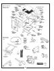
The various parts of the handle assembly P#(A0273)
must be attached to the container frame. (Figure 4)
shows the orientation and location of the components.
Slide the lift handle into the slot in the handle mount
bracket P#(B1730) on the grass container. It may be
necessary to remove the handle grip P#(J0522) to allow
the handle to fit through the slot.
Before attaching the handle, hook one end of the spring
P#(J0176) into the hole on the underside of the handle.
Hook the other end of the spring into the open hole in
the handle mount bracket. Fasten the handle to the
grass container frame by using (1) 3/8”-16 x 2” HHCS
P#(K1208) and (2) 3/8”-16 flange nuts P#(K1215). At this
point the handle can pivot back and forth in the slot of
the handle mount bracket. With the handle in place,
fasten the ball joint P#(K1442), (Figure 5) to the end of
the latch rod P#(A0260). Tighten to approximately half
way down the threads of the latch rod. Slide the ball joint
into the hole on the latch hook P#(B1529). Use (1) 5/16”-
24 hex nut P#(K1444) and (1) 5/16” lock washer
P#(K0043) to fasten the ball joint to the latch hook.
Attach the opposite end of the latch rod into the handle.
Fasten the rod to the handle by using (1) 3/32” x 3/4”
cotter pin P#(K0094). Adjust the rod to allow the hook to
close the box door completely.
Refer to Figures 4,5,6,7, and 8 for exploded parts
drawings and photographs of the complete assembly.
.
IT IS RECOMMENDED FOR THREE PEOPLE
TO ASSIST IN THE MOUNTING OF THE CONTAINER.
With three people available, two can lower the container
onto the frame while the third person inserts the pivot
pins P#(K0172) through the holes. Insert the pins from
the outside to the inside. Secure with (1) 5/8” washer
P#(K0058) and (1) 5/32” x 2-5/8” hair pin clip P#(K0088)
per pivot pin.
Reattach the bottom ends of the door opening linkages
to the main frame by using (1) Rue-Ring cotter pin
P#(K1437) per side.
To test the functionality of the dump mechanism, pull the
lift handle, (Figure 4), away from the unit, and lift
upward. The door of the container should open and the
box should pivot clockwise towards the ground.
NOTE:
The inlet, (Figure 7), will need to be attached to the
container. Open the container, push the inlet, from the
inside of the container through the hole in the container
to the outside. Orient the inlet opening to face the
ground. Use the tabs P#(B1668) inside of the box to hold
the inlet in place. It is recommended that two people
Perform this step. That way, one person on the inside of
the container can position the tabs, while the other
person tightens the bolts. Looking at the outside of the
container, the most difficult tab to tighten down will be
the tab at the 4-5 o’clock position. Tighten that tab first.
Then proceed to tighten the others.
The linkage may be adjusted in two places, at the
adjusting screw P#(K1435) and the latch assembly
items. See (Figures4&7)forvisual clarification. To
change the door closure tightness, screw the adjusting
screw in or out. To adjust the latch, change the length of
the latch rod by screwing the latch adjusting ball joint in
or out. The latch hook pivot should be in the middle of
the slot in the latch hook pivot plate. Slide the pivot back
or forth and then re-tighten.
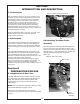
Place the outer engine mount tube P#(B1117) against
the rear of the main frame assembly (Figure 3), with the
hole in the tube to the right hand side of the mower.
Fasten to the main frame assembly by using (2) 3/8” u-
bolts P#(K1432) and (4) 3/8” flange nuts P#(K1215).
2-6 Adjustment Of The Dump
Mechanism
2-7 Attachment Of The Outer Engine
Mount Tube
Figure 3 Outer Engine Mount Tube Attachment
U-bolts