
Grass Collection System Operator's Manual


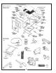


2-9 Engine/Blower/Blade Assembly
Installation
Place the engine/blower/blade assembly onto the engine
mount arm assembly (Figure 11). Secure the
engine/blower blade assembly to the engine mount arm
assembly using (4) 5/16"-18 x 1-1/2" hex bolts
P#(K1157) and (4) 5/16"-18 flange nuts P#(K1178).
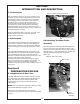
2-8 Engine Mount Arm Installation
Slide the engine mount arm assembly (Figure 10) into
the outer engine mount tube. Secure the engine mount
arm assembly using (1) detent pin P#(J0248).
2-10 Adjustment Of The Hose Length
2-11 Attachment Of The Upper Hose
2-12 Attachment Of The Lower Hose
To The Engine/Blower/Blade Assembly
THE HOSES IN STEPS 2-11 AND 2-12 MUST BE CUT
TO FIT YOUR MACHINE. FOLLOW STEPS 2-11 AND
2-12. DO NOT CUT THE HOSES UNTIL YOU HAVE
TRIED TO FIT THEM ON YOUR MACHINE.
REMEMBER THAT THE HOSES HAVE TO BE LONG
ENOUGH TO ALLOW FOR ENOUGH CLAMPING
SURFACE BETWEEN THE INLET, BLOWER
ASSEMBLY, AND THE DECK BOOT.
Slide a 5”-6” upper hose clamp P#(J6011) onto both
ends of the 6” upper hose (Figure 12). Then slide one
end of the 6” hose onto the inlet. Make sure there is
about a two-inch overlap between the hose end and the
container inlet. Proceed to slide the opposite end of the
6” hose onto the outlet of the blower assembly. See
(Figure 12) for details. Make sure both ends of the hose
are clearly attached to the inlet and the blower assembly
inlet. Tighten the hose clamps.
Slide a 7”-8” hose clamp P#(J6006) over both ends of
the lower hose. Then proceed to slide the lower hose
onto the blower cone. Tighten the hose clamp. The
assembly should look like (Figure 12).
9
Figure 10 Engine Mount Arm
Figure 11 Engine/Blower/Blade Installation
5/16" x 1-1/2" Bolt
Detent Pin
Figure 12 Hose Assembly
Inlet
Upper Hose
Lower Hose
Boot