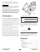
Form No. 3364-811 Rev B Auger Head and Universal Swivel Auger Head for Compact Utility Loaders Model No. 22805—Serial No. 310000001 and Up Model No. 22806—Serial No. 310000001 and Up To register your product or download an Operator's Manual or Parts Catalog at no charge, go to www.Toro.com.
This product complies with all relevant European directives, for details please see the separate product specific Declaration of Conformity (DOC) sheet. DANGER There may be buried power, gas, and/or telephone lines in the work area. Shock or explosion may occur if you dig into them. Have the property or work area marked for buried lines and do not dig in marked areas.
Safety Removing an Auger .............................................. 8 Maintenance................................................................. 9 Recommended Maintenance Schedule(s) .................. 9 Greasing the Cradle Arm Pivot Points ................... 9 Changing Planetary Gear Case Oil ........................ 9 Storage....................................................................... 10 Troubleshooting.........................................................
Stability with a 12 to 30 inch Auger WARNING Important: If you have a traction unit other than a TX compact utility loader, use the counterweight on the traction unit when using the auger drive head with a large auger installed. Failure to use the counterweight will cause the traction unit to become unstable. Lightning can cause severe injury or death. If lightning is seen or thunder is heard in the area, do not operate the machine; seek shelter.
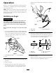
Safety and Instructional Decals Product Overview Safety decals and instructions are easily visible to the operator and are located near any area of potential danger. Replace any decal that is damaged or lost. Figure 3 1. Hose guide 2. Mounting plate 3. Motor 105-0326 4. Cradle arm 5. Drive head 6. Drive shaft Specifications 1. Warning—read the Operator’s Manual. 2. Entanglement hazard, auger—keep bystanders a safe distance from the auger. 3.
Operation Lightly secure the bolt with a flange nut (1/2 inch) (Figure 5). Refer to your traction unit Operator’s Manual for more information on installing and removing attachments on your traction unit. Note: Always use the traction unit to lift and move the attachment. To move an auger without the drive head, sling a strap over each end of the auger and hoist it to the desired location. Installing an Auger WARNING The auger head swings freely in the cradle arms.
Digging a Hole DANGER There may be buried power, gas, and/or telephone lines in the work area. Shock or explosion may occur if you dig into them. Figure 7 1. Drive head Have the property or work area marked for buried lines and do not dig in marked areas. Contact your local marking service or utility company to have the property marked (for example, in the United States, call 811 for the nationwide marking service). 2. Auger shaft 8. Stop the engine. 9.
DANGER If you are using model 22806, excessive downward force may cause the bit to wobble uncontrollably which could tip the traction unit. You or bystanders could be pined or seriously injured. When using model 22806, do not use excessive downward pressure on the bit. Allow the bit to pull itself into the soil. Removing an Auger 1. Raise the loader arms so the auger comes out of the hole.
Maintenance Recommended Maintenance Schedule(s) Maintenance Service Interval Maintenance Procedure After the first 50 hours • Change the planetary gear case oil. Before each use or daily Every 1,000 hours Before storage • Grease the cradle arm pivot points. (Grease all fittings immediately after every washing.) • Check the auger teeth and replace them if they are damaged or worn. • Change the planetary gear case oil. • Check the auger teeth and replace them if they are damaged or worn.
Storage 1. Before long term storage, wash the attachment with mild detergent and water to remove dirt and grime. 2. Check and tighten all bolts, nuts, and screws. Repair or replace any damaged or worn part. 3. Ensure that all hydraulic couplers are connected together to prevent contamination of the hydraulic system. 4. Paint all scratched or bare metal surfaces. Paint is available from your Authorized Service Dealer. 5. Store the attachment in a clean, dry garage or storage area.
Troubleshooting Problem The drive head does not operate. Possible Cause Corrective Action 1. Hydraulic coupler not completely connected 1. Check and tighten all couplers. 2. Defective hydraulic coupler 2. Check couplers and replace any that are defective. 3. Find and remove the obstruction. 4. Replace the kinked hose 5. Refer to your authorized service dealer. 3. An obstruction in a hydraulic hose 4. Kinked hydraulic hose 5.
Toro Compact Utility Equipment Warranty A One-Year Limited Warranty Conditions and Products Covered The Toro® Company and its affiliate, Toro Warranty Company, pursuant to an agreement between them, jointly warrant your Toro Compact Utility Equipment (“Product”) to be free from defects in materials or workmanship.