
Service Manual

3
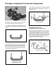
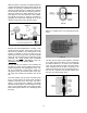
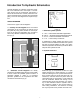
When the piston in the pump is pushed downward,
oil will be directed past a second check ball into the
cylinder. As the pump is actuated up and down, the
incoming oil will cause the cylinder ram to extend.
The lift cylinder will hold its extended position be-
cause the check ball is being seated by the pres-
sure against it from the load side of the cylinder.
The cylinder will return to neutral by unseating or
bypassing the check balls, allowing the oil in the
cylinder to return back to the reservoir (Fig.6)
Because the pump displacement is usually much
smaller than the cylinder, each stroke of the pump
will move the cylinder a very small amount. If the
cylinder is required to move at a faster rate, the
surface area of the pump piston must be increased
and/or the rate which the pump is actuated must be
increased. OIL FLOW GIVES THE CYLINDER
RAM ITS SPEED OF MOVEMENT AND OIL
PRESSURE CREATES WORK FORCE.
We can improve the efficiency and Increase the
versatility of a basic circuit by adding some sophis-
ticated components and changing the circuit lay-
out. By incorporating a gear pump in place of a
hand piston pump, we increase oil flow to the cylin-
der which will increase the actuation rate of the
ram.
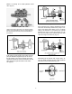
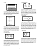
The most common type of pump is the gear pump
(Fig 7). As the gears in the pump rotate, suction is
created at the inlet port of the pump. The fluid is
drawn in to the pump and is carried in the spaces
between the gear teeth to the discharge port of the
pump. At the discharge side of the pump the gear
teeth mesh together and the oil is discharged from
the pump.
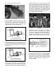
Below is a cutaway view of an actual three section
pump.
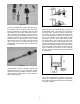
The flow from the pump to the cylinder is controlled
by a sliding spool valve which can be actuated by
an electric solenoid, or a hand or foot operated
lever. The valve shown in Figure 9 is a open center
valve, meaning that the oil flow is returned to the
reservoir when the valve is in the neutral position. If
the oil flow is stopped in the neutral position than
the valve is a closed center valve.
Figure 6
Figure 7
Figure 8
Figure 9