
Service Manual

4
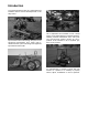
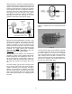
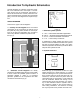
Below is a cutaway of an actual hydraulic control
valve (Fig 10).
Here we see have a spool valve in our simple hydraulic
system, we can see that the valve is in the neutral posi-
tion and all the flow from the pump is directed back to
the reservoir.
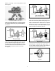
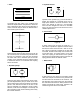
If the spool is moved upward, the oil flow from the
pump is directed through the spool to one end of
the lift cylinder. The oil in the opposite end of the
cylinder is pushed out as the ram extends, and will
pass through the spool and return to the reser-
voir.(Fig 12).
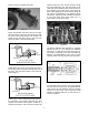
Since the fluid from a positive displacement pump
must flow continuously whenever the pump is run-
ning it must have some where to go if not being
used by the actuators. If the load on the cylinder
becomes too great or if the ram bottoms out, the
flow from the pump will be directed past the relief
valve returning to the reservoir (Fig 13).
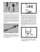
Substituting the lift cylinder with a gear motor, we
can now utilize out basic circuit to create rotational
movement to drive attachments (Fig 14).
Figure 12
Figure 10
Figure 11
Figure 13
Figure 14