Form No. 3422-267 Rev A TRX-16, TRX-20, and TRX-26 Trencher Model No. Model No. Model No. Model No. Model No. Register at www.Toro.com. Original Instructions (EN) 22972—Serial No. 402461470 and Up 22972G—Serial No. 402000000 and Up 22973—Serial No. 402501800 and Up 22973G—Serial No. 402000000 and Up 22974—Serial No.
Introduction This product complies with all relevant European directives; for details, please see the separate product specific Declaration of Conformity (DOC) sheet. This machine is designed to dig trenches in soil to bury cabling and piping for various applications. It is not intended to cut rock, wood, or any other material other than soil.
Replacing the Fuses (Models 22973 and 22974)........................................................... 34 Drive System Maintenance .................................. 34 Servicing the Tracks ......................................... 34 Belt Maintenance ................................................ 37 Replacing the Pump-Drive Belt ......................... 37 Controls System Maintenance ............................. 37 Adjusting the Traction-Control Alignment...............................................
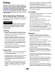
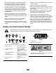
Safety • Inspect the area where you will use the equipment and remove all objects, such as rocks, toys, and wire, that the machine could throw. Improper use or maintenance by the operator or owner can result in injury. To reduce the potential for injury, comply with these safety instructions and always pay attention to the safety-alert symbol (Figure 2), which means Caution, Warning, or Danger—personal safety instruction. Failure to comply with the instruction may result in personal injury or death.
• • • • • • • • • • • • and remove the key before leaving the operator's position for any reason. Keep your hands and feet away from moving parts. Look behind and down before backing up to ensure that the path is clear. Never carry passengers and keep pets and bystanders away. Do not operate the machine when you are tired, ill, or under the influence of alcohol or drugs. Use care when loading or unloading the machine into a trailer or truck. Use care when approaching blind corners.
• Keep all nuts and bolts tight. Keep the equipment • Disconnect the battery or remove the spark-plug wires before making any repairs. Disconnect the negative terminal first and the positive last; connect the positive first and the negative last. in good condition. • Never tamper with the safety devices. • Keep the machine free of debris buildup. Wipe up • Charge the battery in an open, well-ventilated any spilled oil or fuel. Allow the machine to cool before storing. area, away from spark and flames.
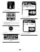
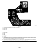
decal93-9084 93-9084 1. Lift point/Tie-down point decal137-3873 137-3873 1. Read the Operator’s Manual. decal100-4650 100-4650 1. Crushing hazard of hand—keep bystanders a safe distance away from the machine. 2. Crushing hazard of foot—keep bystanders a safe distance away from the machine. decal107-8495 107-8495 decal137-3874 1. Parking brake 137-3874 1. Read the Operator’s Manual.
decal115-4020 115-4020 1. Turn right 3. Reverse 2. Forward 4. Turn left decal99-9952 99-9952 1. Cutting hazard, chain and auger—stay away from moving parts and keep bystanders away from the machine. 2. Warning—shut off the engine and remove the key before preforming and maintenance or repairs. 3. Explosion and/or electric shock hazard—do not dig in areas with buried gas or power lines.
decal115-1230 115-1230 1. Warning—do not operate this machine unless you are trained. 2. Engine—stop 3. Engine—run 4. 5. 6. 7. 8. 9. 10. 11. 12. Trencher chain—reverse Trencher chain—forward Trencher chain—off Engine throttle Fast Slow Choke On/Closed Off/Open 13.
decal115-1231 115-1231 1. Cutting/dismemberment hazard of bystanders, trencher—keep bystanders a safe distance away from the machine; do not operate the trencher chain while transporting the machine. 2. Explosion hazard, fueling—shut off the engine and extinguish all flames when fueling. 6. Explosion hazard; shock hazard—do not use machine near buried utility lines; contact the proper agencies before digging. 3. Tipping/crushing hazard—lower the boom when operating on slopes. 8. Lower the boom 4.
Setup Loose Parts Use the chart below to verify that all parts have been shipped. Procedure 1 2 3 Description Use Qty. Boom (sold separately) Chain (sold separately) 1 1 Install the boom and chain. No parts required – Check the fluid levels. No parts required – Charge the battery (electric-start models only).
10. Loop the digging chain over the auger drive shaft and onto the drive sprocket, ensuring that the digging teeth point forward on the upper span. 11. Set the upper span of the chain into place on the trencher boom, then wrap the chain around the roller at the end of the boom. 12. Thread the adjustment bolt into the boom and turn it in until there is 3.8 to 6.3 cm (1-1/2 to 2-1/2 inches) of slack in the chain on the bottom span. 13.
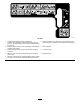
Key Switch Traction Control Recoil-Start Machines The key switch has 2 positions: OFF and RUN. Refer to Starting the Engine (page 17). Electric-Start Machines The key switch has 3 positions: OFF, RUN, and START . Refer to Starting the Engine (page 17). g008128 Figure 6 Throttle Lever 1. Reference bar 2. Traction control Move the control forward to increase the engine speed and rearward to decrease the engine speed. • To move forward, move the traction control forward (Figure 7).
• To turn right, rotate the traction control clockwise (Figure 9). g008131 Figure 9 g007802 • To turn left, rotate the traction control Figure 11 counterclockwise (Figure 10). 1. Lower the boom 2. Raise the boom Boom-Elevation Lock The boom-elevation lock secures the boom-elevation lever so that you cannot push it forward. This helps to ensure that no one accidentally lowers the boom during maintenance. Secure the boom with the lock anytime you need to stop the machine with the boom raised.
Trencher Control Lever Specifications To dig with the trencher, rotate the lever rearward and pull it down to the reference bar (Figure 13, number 1). Note: Specifications and design are subject to change without notice. To reverse the trencher head, rotate the lever rearward, then move it left into the upper slot (Figure 13, number 2). Width If you release the lever, it will automatically return to the neutral position (Figure 13, number 3), stopping the chain. Length with 91.
Operation DANGER In certain conditions during fueling, static electricity can be released, causing a spark that can ignite the fuel vapors. A fire or explosion from fuel can burn you and others and can damage property. • Always place fuel containers on the ground away from your vehicle before filling. • Do not fill fuel containers inside a vehicle or on a truck or trailer bed, because interior carpets or plastic truck bed liners may insulate the container and slow the loss of any static charge.
• Do not store fuel either in the fuel tank or fuel containers over the winter unless you use a fuel stabilizer. Do not add oil to gasoline. • 5. Install the fuel-tank cap securely. 6. Wipe up any spilled fuel.
5. Move the throttle lever to the desired setting (Figure 16). CAUTION A child or untrained bystander could attempt to operate the machine and be injured. Important: Running the engine at high speeds when the hydraulic system is cold (i.e., when the air temperature is at or below freezing) could damage the hydraulic system. When starting the engine in cold conditions, allow it to run in the middle throttle position for 2 to 5 minutes before moving the throttle to the FAST position.
Securing the Machine for Transport the chain and lower it fully. Start the chain again and resume operation. 4. Once the trencher boom is in the ground at a 45° to 60° angle, slowly move the machine rearward to extend the trench. Important: Do not operate or drive the machine on roadways. Use care when loading or unloading the machine into a trailer or truck. Note: If you move too fast, the trencher will stall.
Operating Tips • Use the correct chain for the ground conditions, as listed in the following table: • Clean the area of trash, branches, and rocks before trenching to prevent damaging the machine. • Always begin trenching with the slowest ground speed possible. Increase speed if conditions permit. If the chain speed slows down, reduce the ground speed to keep the chain moving at its fastest rate. Do not spin the tracks while trenching. • Always use full throttle (maximum engine speed) when trenching.
Maintenance Note: Determine the left and right sides of the machine from the normal operating position. Recommended Maintenance Schedule(s) Maintenance Service Interval Maintenance Procedure After the first 8 hours • Change the engine oil. After the first 50 hours • Check and adjust the track tension. Before each use or daily • • • • • • Grease the machine. (Grease immediately after every washing.) Check the engine-oil level. Check the condition of and clean the tracks.
CAUTION If you leave the key in the key switch, someone could accidently start the engine and seriously injure you or other bystanders. Remove the key from the key switch and disconnect the wires from the spark plugs before you do any maintenance. Set the wires aside so that they do not accidentally contact the spark plugs. Pre-Maintenance Procedures Important: The fasteners on the covers of this machine are designed to remain on the cover after removal.
Lubrication Removing the Bottom Shield 1. Greasing the Machine Park the machine on a level surface, engage the parking brake (if applicable), and lower the hydraulic lift. 2. Shut off the engine and remove the key. 3. Loosen the 2 bolts securing the bottom shield sequentially until the shield is free (Figure 22). Service Interval: Before each use or daily (Grease immediately after every washing.) Grease Type: General-purpose grease. g011472 1.
Greasing the Trencher Housing Service Interval: Every 40 hours Grease Type: General-purpose grease. g007823 1. Park the machine on a level surface, engage the parking brake, and lower the hydraulic lift. 2. Shut off the engine and remove the key. 3. Clean the trencher housing grease fitting with a rag and connect a grease gun to it (Figure 27). Figure 25 g008334 Figure 27 g007824 Figure 26 24 4.
Engine Maintenance Servicing the Air Cleaner Models 22972 and 22973 Service Interval: Every 25 hours—Clean the foam air-cleaner element (more often in dirty or dusty conditions)—Models 22972 and 22973 only. Every 100 hours—Check the paper air-cleaner element (more often in dirty or dusty conditions)—Models 22972 and 22973 only. Every 200 hours/Yearly (whichever comes first)—Replace the paper air-cleaner element (more often in dirty or dusty conditions)—Models 22972 and 22973 only. g012619 Figure 28 1.
Model 22974 Servicing the Primary Filter Service Interval: Every 250 hours (more often in dirty or dusty conditions)—Model 22974 only. Inspect the primary filter for damage by looking into the filter while shining a bright light on the outside of the filter. Note: Holes in the filter appear as bright spots. If Every 500 hours (more often in dirty or dusty conditions)—Model 22974 only. the filter is dirty, bent, or damaged, replace it. Do not clean the primary filter. Removing the Filters 1.
Checking the Engine-Oil Level Servicing the Engine Oil Service Interval: After the first 8 hours—Change the engine oil. Before each use or daily—Check the engine-oil level. 1. Park the machine on a level surface, engage the parking brake (if applicable), and lower the hydraulic lift. 2. Shut off the engine and remove the key. Every 100 hours—Change the engine oil. Every 200 hours—Change the engine-oil filter.
Changing the Engine Oil 1. Start the engine and let it run 5 minutes. This warms the oil so it drains better. 2. Park the machine so that the drain side is slightly lower than the opposite side to ensure that the oil drains completely. 3. Lower the boom and engage the parking brake. 4. Shut off the engine, remove the key, and wait for all moving parts to stop before leaving the operating position. 5. Place a pan below the drain hose.
Changing the Engine-Oil Filter Servicing the Spark Plug 1. Drain the oil from the engine; refer to Changing the Engine Oil (page 28). Service Interval: Every 100 hours 2. Change the engine-oil filter (Figure 34). Make sure that the air gap between the center and side electrodes is correct before installing the spark plug. Use a spark plug wrench for removing and installing the spark plug(s) and a gapping tool/feeler gauge to check and adjust the air gap. Install a new spark plug(s) if necessary.
Checking the Spark Plug Fuel System Maintenance Important: Do not clean the spark plug(s). Always replace the spark plug(s) when it has: a black coating, worn electrodes, an oily film, or cracks. Draining the Fuel Tank If you see light brown or gray on the insulator, the engine is operating properly. A black coating on the insulator usually means the air cleaner is dirty. DANGER In certain conditions, fuel is extremely flammable and highly explosive.
Replacing the Fuel Filter Electrical System Maintenance Service Interval: Every 200 hours Never install a dirty filter if it is removed from the fuel line. Servicing the Battery Note: Note how the fuel filter is installed in order to install the new filter correctly. Electric-Start Machines Only Note: Wipe up any spilled fuel. Service Interval: Every 25 hours—Check the battery electrolyte level. 1. Park the machine on a level surface, engage the parking brake, and lower the hydraulic lift. 2.
WARNING Battery terminals or metal tools could short against metal components, causing sparks. Sparks can cause the battery gasses to explode, resulting in personal injury. • When removing or installing the battery, do not allow the battery terminals to touch any metal parts of the traction unit. 2. Shut off the engine and remove the key. 3. Lift the black rubber cover on the negative cable. Disconnect the negative battery cable from the negative (-) battery terminal (Figure 40). 5.
Checking the Battery Electrolyte Level DANGER Battery electrolyte contains sulfuric acid which is fatal if consumed and causes severe burns. • Do not drink electrolyte and avoid contact with skin, eyes or clothing. Wear safety glasses to shield your eyes and rubber gloves to protect your hands. • Fill the battery where clean water is always available for flushing the skin. 1. Park the machine on a level surface, engage the parking brake, and lower the hydraulic lift. 2.
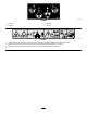
Replacing the Fuses (Models 22973 and 22974) Drive System Maintenance There are 4 fuses in the electrical system. They are under the control panel on the left side (Figure 43). 30 25 15 15 Start Circuit Charge Circuit Cooler fan Circuit Headlight (optional) Servicing the Tracks amp amp amp amp Cleaning the Tracks Service Interval: Before each use or daily Check the tracks for excessive wear and clean them periodically. If the tracks are worn, replace them. g015381 Figure 43 1.
Checking and Adjusting the Track Tension is applied to the track span. Adjust the torque on the tensioning bolt as needed. Service Interval: After the first 50 hours Every 100 hours To check the tension of each track, place 20.4 kg (45 lb) on the track midway between the front road wheel and the drive sprocket. The track should flex no more than 0.6 to 1 cm (1/4 to 3/8 inch). If it does, adjust the track tension using the following procedure: 6. Tighten the jam nut. 7.
Checking and Greasing the Road Wheels Service Interval: Every 250 hours g242269 1. Park the machine on a level surface, engage the parking brake, and lower the hydraulic lift. 2. Shut off the engine and remove the key. 3. Remove the tracks; refer to Replacing the Tracks (page 35). 4. Remove the snap ring and cap from a road wheel (Figure 49). Figure 48 1. Snap ring 4. Gasket 2. Cap 5. Wheel with bearings 3. Bolt 8. When the track is off the road wheel, remove it from the machine (Figure 47).
Belt Maintenance Controls System Maintenance Replacing the Pump-Drive Belt Adjusting the Traction-Control Alignment If the pump drive belt begins to squeal or is cracked, worn, or frayed, replace it. Contact your Authorized Service Dealer for a replacement belt. The factory adjusts the traction controls before shipping the machine.
g004191 Figure 52 1. Traction control 5. 2. Stem, bolt, and nut Adjust the traction control so that it rests flush against the reference bar when it is pulled straight back (Figure 52 and Figure 53). g011476 Figure 54 1. Traction rod E. 2. Jam nut Start the machine and set the throttle to about the 1/3 open position. WARNING When the machine is running, you could be caught and injured in moving parts or burned on hot surfaces. g004192 Figure 53 6.
Adjusting the Traction-Control Neutral Position Hydraulic System Maintenance If the machine creeps forward or backward when the traction control is in neutral and the machine is warm, you may need to adjust the return-to-neutral mechanism on the pumps; contact your Authorized Service Dealer. WARNING Hydraulic fluid escaping under pressure can penetrate skin and cause injury.
Industry Standards API GL-4, AGCO Powerfluid 821 XL, Ford New Holland FNHA-2-C-201.00, Kubota UDT, John Deere J20C, Vickers 35VQ25 and Volvo WB-101/BM Note: Many hydraulic fluids are almost colorless, making it difficult to spot leaks. A red dye additive for the hydraulic system fluid is available in 20 ml (0.67 fl oz) bottles. One bottle is sufficient for 15 to 22 L (4 to 6 US gallons) of hydraulic fluid. Order Part No. 44-2500 from your Authorized Toro Dealer.
5. Install the replacement hydraulic filter and filler cap (Figure 58) and torque the bolt on top to 13 to 15.5 N∙m (110 to 140 in-lb). 6. Clean up any spilled fluid. 7. Install the top cover. Changing the Hydraulic Fluid Service Interval: Every 400 hours/Yearly (whichever comes first) 1. Park the machine on a level surface, engage the parking brake (if applicable), and lower the hydraulic lift. 2. Shut off the engine and remove the key. 3. Allow the machine to cool completely. 4.
Trencher Maintenance Replacing the Digging Teeth Service Interval: Before each use or daily—Check the condition of the digging teeth and replace any that are worn or damaged. Due to the high amount of wear placed on the digging teeth, you will need to replace them periodically. g007841 Figure 60 1. Bolts 2. Jam nut 3. Adjusting bolt To replace a single tooth, remove the bolts securing the tooth to remove it, then install a new tooth in the same position.
12. 7. Tighten the jam nut. 8. Torque the 2 bolts and nuts securing the boom to 183 to 223 N∙m (135 to 165 ft-lb). Slide the new sprocket onto the shaft (Figure 61). Important: The arrow on the sprocket face should be visible from the right side of the trench and should point in a clockwise direction; if not, turn the sprocket around. Replacing the Drive Sprocket Over time, the drive sprocket wears, especially when it is used in sandy or clay soils.
Cleaning Storage Removing Debris from the Machine Important: Operating the engine with blocked screens, dirty or plugged cooling fins, and/or cooling shrouds removed will result in engine damage from overheating. 1. Park the machine on a level surface, engage the parking brake, and lower the hydraulic lift. 2. Shut off the engine, remove the key, and wait for the engine to cool. 3. Remove dirt and grime from the external parts of the entire machine, especially the engine.
9. With the spark plug removed from the engine, pour 2 tablespoons of engine oil into the spark-plug hole. 10. Place a rag over the spark-plug hole to catch any oil spray, then use the starter or recoil handle to crank the engine and distribute the oil inside the cylinder. 11. Install the spark plug, but do not install the wire on the spark plug. 12. Charge the battery (electric-start machines only); refer to Charging the Battery (page 32). 13.
Troubleshooting Problem The starter does not crank (electric-start machines only). The engine does not start, starts hard, or fails to keep running. The engine loses power. Possible Cause Corrective Action 1. The battery is discharged. 1. Charge the battery or replace it. 2. The electrical connections are corroded or loose. 3. The relay or switch is damaged. 2. Check the electrical connections for good contact. 3. Contact your Authorized Service Dealer. 1. The fuel tank is empty. 1.
Problem The trencher does not dig fast enough. Possible Cause Corrective Action 1. The digging teeth are worn. 1. Replace the digging teeth. 2. The chain you are using is not appropriate for the type of ground. 3. The hydraulic system is overheated. 2. Evaluate the ground type and change chains if necessary. 3. Shut down and allow the system to cool. 4. Contact your Authorized Service Dealer. 4. The hydraulic system is obstructed, contaminated, or damaged.
Schematics g015383 Electrical Schematic—Model 22972 (Rev.
g015384 Electrical Schematic—Model 22973 (Rev.
g015439 Electrical Schematic—Model 22974 (Rev.
g028603 Hydraulic Schematic (Rev.
Notes:
Notes:
Notes:
European Privacy Notice The Information Toro Collects Toro Warranty Company (Toro) respects your privacy. In order to process your warranty claim and contact you in the event of a product recall, we ask you to share certain personal information with us, either directly or through your local Toro company or dealer. The Toro warranty system is hosted on servers located within the United States where privacy law may not provide the same protection as applies in your country.
California Proposition 65 Warning Information What is this warning? You may see a product for sale that has a warning label like the following: WARNING: Cancer and Reproductive Harm—www.p65Warnings.ca.gov. What is Prop 65? Prop 65 applies to any company operating in California, selling products in California, or manufacturing products that may be sold in or brought into California.