Form No. 3443-247 Rev C Backhoe Compact Tool Carrier Model No. 23106—Serial No. 321000001 and Up Register at www.Toro.com.
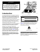
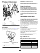
WARNING CALIFORNIA Proposition 65 Warning Use of this product may cause exposure to chemicals known to the State of California to cause cancer, birth defects, or other reproductive harm. Introduction g352049 Figure 1 1. Model and serial number location The backhoe attachment is intended to be used on a Toro compact tool carrier. It is designed primarily for digging soil for various applications at jobsites.
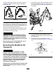
Safety • DANGER There may be buried utility lines in the work area. Digging into them may cause a shock or an explosion. • Have the property or work area marked for buried lines and do not dig in marked areas. Contact your local marking service or utility company to have the property marked (for example, in the US, call 811 or in Australia, call 1100 for the nationwide marking service). • General Safety • Always follow all safety instructions to avoid serious injury or death.
• Do not overload the machine capacity by Maintenance and Storage Safety attempting to use the backhoe too fast. • Check fasteners at frequent intervals for proper • Do not dig within 91 cm (3 ft) of the backhoe or stabilizers. tightness to ensure that the equipment is in safe operating condition. • Check for overhead clearance (i.e., electrical wires, branches, and doorways) before driving under any objects and do not contact them.
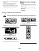
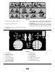
decal145-1851 145-1851 4. Tipping hazard—do not move the traction unit while seated on the backhoe; install the counterweight (if applicable); lower the stabilizers. 5. Explosion and electric shock hazards—call your local utility company before digging; do not dig in areas with buried gas or electrical lines; do not operate under overhead electrical lines. 1. Warning—read the Operator’s Manual. 2. Warning—keep bystanders away. 3. Crushing hazard, backhoe—lock the boom before leaving the machine.
Setup 3 You must obtain and install the Backhoe Kit appropriate for your traction unit. Use the instructions provided in this section to install these kits. Adjusting the Seat 1 No Parts Required Procedure Preparing the Machine CAUTION The seat mounting bracket has several pinch points. You could pinch and/or cut your fingers when adjusting the seat. No Parts Required Procedure 1. Park the machine on a level surface. 2. Engage the parking brake. 3. Lower the loader arms. 4.
Stabilizer Control Levers Product Overview Move the stabilizer control levers forward to lower the stabilizers and backward to raise the stabilizers. Boom Control Lever Move the boom control lever forward to lower the boom and backward to raise the boom. Move the boom control lever to the right to swing the boom to the right and move it left to swing the boom to the left. You can also move the boom control lever into an intermediate position (i.e.
Attachments/Accessories Operation A selection of the manufacturer approved attachments and accessories is available for use with the machine to enhance and expand its capabilities. Contact your Authorized Service Dealer or authorized the manufacturer distributor or go to www.Toro.com for a list of all approved attachments and accessories. WARNING Hydraulic fluid escaping under pressure can penetrate skin and cause injury.
WARNING If you do not fully seat the quick-attach pins through the attachment mount plate, the attachment could fall off the machine, crushing you or bystanders. Ensure that the quick-attach pins are fully seated in the attachment mount plate. Preparing for Operation 1. Drive to the work location. 2. If you are using the backhoe with a TX1000, ensure that the hook-and-loop strap (provided in the Fit-Up Kit) is installed on the control panel; refer to the Fit-Up Kit Installation Instructions.
To empty the bucket, swing it to the left or right and extend the dipper and uncurl bucket, dumping the load (Figure 10). 1. Fully raise the boom, retract the dipper, and curl the bucket rearward (Figure 11). Ensure that you center the boom locking pin holes as much as possible. g348211 Figure 10 The distance you extend the dipper and bucket and the size of bite you take will vary greatly with the soil type, moisture content of the soil, and obstructions in the soil, such as tree roots and rocks.
g352158 Figure 13 1. Pin Operating Tips • Do not take large bites of soil. Instead, sweep the bucket through the soil using the swinging motion of the dipper a few inches deep at a time. • If the bucket catches in the soil, uncurl the bucket, raise the boom slightly, and continue digging. • If your traction unit has a speed selector, set it to the slow (turtle) position while you are learning how to operate the backhoe (this will slow the backhoe down).
Maintenance Recommended Maintenance Schedule(s) Maintenance Service Interval After the first hour Maintenance Procedure • Check all bolts and nuts for proper tightness and tighten them if needed. Before each use or daily • Grease all fittings. Every 25 hours • Inspect for leaks. Before storage • Grease all fittings. • Wash the backhoe. • Paint all scratched or bare metal surfaces. Greasing the Backhoe Service Interval: Before each use or daily—Grease all fittings.
Storage 1. Before long term storage wash the attachment with mild detergent and water to remove dirt and grime. 2. Apply grease to all grease fittings. 3. Check and tighten all bolts, nuts, and screws. Repair or replace any parts that are damaged or worn. 4. Paint all scratched or bare metal surfaces. Note: Paint is available from your Authorized Service Dealer. 5. g352087 Figure 15 g352076 Figure 16 13 Store the attachment in a clean, dry garage or storage area.
Troubleshooting Problem The backhoe does not operate. Possible Cause 1. The hydraulic coupler not completely connected. 1. Check and tighten all couplers. 2. The auxiliary-hydraulics valve on the traction unit is not fully engaged. 3. The transport pins were not removed. 4. The hydraulic-fluid level is low. 5. A hydraulic coupler is damaged. 2. Engage the valve. 6. A hydraulic hose is obstructed. 7. A hydraulic hose is pinched. 8. The auxiliary-hydraulic valve on the traction unit is not opening. 9.
Declaration of Incorporation The Toro Company, 8111 Lyndale Ave. South, Bloomington, MN, USA declares that the following unit(s) conform(s) to the directives listed, when installed in accordance with the accompanying instructions onto certain Toro models as indicated on the relevant Declarations of Conformity. Model No. 23106 Serial No.
California Proposition 65 Warning Information What is this warning? You may see a product for sale that has a warning label like the following: WARNING: Cancer and Reproductive Harm—www.p65Warnings.ca.gov. What is Prop 65? Prop 65 applies to any company operating in California, selling products in California, or manufacturing products that may be sold in or brought into California.