Form No. 3447-314 Rev A Concrete Breaker Compact Tool Carriers Model No. 23136—Serial No. 321000001 and Up Register at www.Toro.com.
WARNING CALIFORNIA Proposition 65 Warning Use of this product may cause exposure to chemicals known to the State of California to cause cancer, birth defects, or other reproductive harm. Introduction g360512 Figure 1 This concrete breaker is intended to be used on a Toro compact tool carrier. It is designed primarily for breaking concrete, asphalt, rock, or brick during renovation jobs. 1.
Contents Safety Safety ....................................................................... 3 General Safety ................................................... 3 Slope Safety ....................................................... 4 Concrete Breaker Safety .................................... 4 Maintenance and Storage Safety........................ 4 Safety and Instructional Decals .......................... 5 Setup ........................................................................
Slope Safety Concrete Breaker Safety • Operate the machine up and down slopes with • Wear personal protective equipment (PPE) and the heavy end of the machine uphill. Weight distribution changes with attachments. This attachment makes the front of machine the heavy end. appropriate clothing, including the following: – Hard hat – Respirator or dust mask • Keep the attachment in the lowered position – Safety glasses when on slopes.
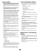
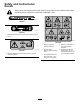
Safety and Instructional Decals Safety decals and instructions are easily visible to the operator and are located near any area of potential danger. Replace any decal that is damaged or lost. decal133-8061 133-8061 decal145-3751 145-3751 1. Read the Operator’s Manual; grease the machine every 3 hours. decal145-3753 145-3753 decal145-3752 145-3752 1. Warning—Maximum pressure 8 bar (116 psi); read the Operator’s Manual. 1. Warning—read the Operator’s Manual. 4.
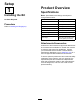
Setup Product Overview 1 Specifications Installing the Bit Note: Specifications and design are subject to change without notice. No Parts Required Width 63 cm (24.8 inches) Length 130 cm (51.2 inches) Procedure Height 33 cm (13.0 inches) Refer to Installing the Bit (page 8). Weight 176 kg (389 lb) Bit working length 29 cm (11.4 inches) Bit diameter 5 cm (2 inches) Impact energy class 339 J (250 ft-lb) Impact rate 600 to 1150 bpm Flow range 20 to 35 L per minute (5.3 to 8.
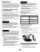
Operation CAUTION Hydraulic couplers, hydraulic lines/valves, and hydraulic fluid may be hot. If you contact hot components, you may be burned. • Wear gloves when disconnecting the hydraulic couplers. • Allow the machine to cool before touching hydraulic components. • Do not touch hydraulic fluid spills. Important: For 300 series traction units, ensure that you install the Relief Valve Kit on your traction unit before using the breaker. Failure to install the kit may damage your traction unit.
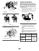
12. Remove the bit. g358958 g359828 Figure 4 1. Bit pin remover Figure 7 3. Stopper plug 2. Stopper pin 7. Installing the Bit From the opposite side of the retainer pin plugs, use a hammer and the bit pin remover to remove the 2 retainer pin plugs. Note: Do not remove the retainer pins; 1. Ensure that the concrete breaker rests on the ground. 2. Grease the bit and inside of the bit bushing. otherwise the bit may fall out. g358954 Figure 8 g359829 1. Bit bushing Figure 5 1.
Testing the Breaker Important: After installing the breaker on a machine, especially after storage, always test it before you break material to release air from the oil circuit. Using the breaker suddenly without releasing the air breaks the oil film and causes the breaker to seize. 1. Park the machine on a level surface and engage the parking brake (if applicable). 2. Raise the loader arms and tilt the breaker so that it is vertical. Ensure that the bit does not touch the ground. g358956 Figure 10 1.
Breaking Material Breaking a Vertical Surface Important: Continuously impacting the same location for long periods of time creates high temperatures at the tip of the bit. This could cause the bit to lose its temper and mushroom under impact, destroying the bit. 1.
Operating Tips – Never pry with the bit of the breaker. • If the bit is positioned too far from the edge of the – Avoid hitting material abruptly with the bit. material, the material may absorb the energy and not break. – Do not use the breaker to lift or move material. – Do not operate the breaker under water; only allow the bit into water. • If the material does not break after 1 minute, stop the breaker and move the bit to a different location.
Maintenance CAUTION If you leave the key in the ignition switch, someone could accidently start the engine and seriously injure you or other bystanders. Remove the key from the ignition before you do any maintenance. Recommended Maintenance Schedule(s) Maintenance Service Interval Before each use or daily Maintenance Procedure • Grease the bit. Grease every 3 hours of operation and after every washing.
Checking the Nitrogen Charge Service Interval: Every 100 hours—Check the nitrogen charge in the accumulator. 4. Insert a pressure gauge into the gas valve and measure it. 5. If it is low, contact your Authorized Service Dealer to charge it. Checking the Hydraulic Lines WARNING Within the breaker is a chamber containing pressurized nitrogen, which under the right circumstances could explode, injuring or killing you or bystanders.
Storage 8. Storing the Attachment 1. 2. Park the machine on a level surface and engage the parking brake (if applicable). If the attachment will be stored for more than 30 days, release the gas pressure from the attachment: A. Remove the bit; refer to Removing the Bit (page 7) B. Release the nitrogen gas from the cylinder cover through the gas valve. Place the breaker on 2 pieces of wood so that the cylinder side is higher than the chisel holder side. g359805 Figure 21 1. Gas valve C.
Troubleshooting Problem Hydraulic fluid is leaking. Possible Cause 1. An oil seal, O-ring, or backup ring is worn or damaged. 1. Contact your Authorized Service Dealer. 2. The piston or cylinder has seized. 2. Contact your Authorized Service Dealer. 3. Tighten the loose part. 3. The tie rod nut, choke plug, or hose adapter is loose. More than 10 bar (145 psi) of nitrogen gas leaks every 100 hours. Corrective Action 1. An O-ring, piston, or seal is worn or damaged. 1.
Notes:
Notes:
Declaration of Incorporation The Toro Company, 8111 Lyndale Ave. South, Bloomington, MN, USA declares that the following unit(s) conform(s) to the directives listed, when installed in accordance with the accompanying instructions onto certain Toro models as indicated on the relevant Declarations of Conformity. Model No. 23136 Serial No.
EEA/UK Privacy Notice Toro’s Use of Your Personal Information The Toro Company (“Toro”) respects your privacy. When you purchase our products, we may collect certain personal information about you, either directly from you or through your local Toro company or dealer.
California Proposition 65 Warning Information What is this warning? You may see a product for sale that has a warning label like the following: WARNING: Cancer and Reproductive Harm—www.p65Warnings.ca.gov. What is Prop 65? Prop 65 applies to any company operating in California, selling products in California, or manufacturing products that may be sold in or brought into California.