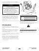
Form No. 3404-531 Rev A 18in Dethatcher Model No. 23513—Serial No. 316000001 and Up g025335 Register at www.Toro.com.
This product complies with all relevant European directives; for details, please see the separate product specific Declaration of Conformity (DOC) sheet. WARNING CALIFORNIA Proposition 65 Warning This product contains a chemical or chemicals known to the State of California to cause cancer, birth defects, or reproductive harm. The engine exhaust from this product contains chemicals known to the State of California to cause cancer, birth defects, or other reproductive harm. 1 g025340 Figure 1 1.
Contents Safety Safety ........................................................................... 3 Safe Operating Practices........................................... 3 Safety and Instructional Decals ................................. 4 Setup ............................................................................ 6 Unfolding the Handle .............................................. 6 Checking the Engine-Oil Level.................................. 6 Product Overview .................................
Operation Slope Operation • Never run an engine in an enclosed area. • Only operate in good light, keeping away from holes and • Do not operate on slopes when grass is wet. Slippery hidden hazards. • • Start the engine only from the operator’s position. • Never operate without the shields, covers, or other guards • securely in place. Be sure all interlocks are functioning properly.
125-3809 1. Warning—read the Operator’s Manual. 5. Thrown object hazard—keep bystanders away from the machine. 2. Warning—do not operate this machine unless you are trained. 6. Warning—shut off the engine before walking away from the machine. 3. Thrown object hazard—shut off the engine and remove any 7. Warning—shut off the engine and disconnect the spark plug debris from your path. wire before performing maintenance on the machine. 4. Warning—stay away from moving parts; keep all guards in place.
Setup Product Overview 2 Unfolding the Handle 1 1. Raise the handle to the operating position (Figure 3). 3 4 6 5 g025337 Figure 4 1. Operator-presence bail 4. Fuel tank 2. Handle 5. Depth-control lever 3. Throttle-control lever 6. Recoil-starter handle g025336 Figure 3 Controls 2. Slide the oval locking rings down each side of the upper handle over the lower handle, locking the handle sections together (Figure 3).
Recoil Starter Pull the recoil-starter handle to start the engine (Figure 5). Fuel-Shutoff Valve Close the fuel-shutoff valve when transporting or storing the machine (Figure 5). Choke Lever Before starting a cold engine, move the choke lever forward. After the engine starts, regulate the choke to keep the engine running smoothly. As soon as possible, move the choke lever all the way rearward. Note: A warm engine requires little or no choking.
Throttle Lever Move the control forward to increase the engine speed, and rearward to decrease speed (Figure 7). 1 2 3 4 g025338 Figure 8 1. Depth-control lever 3. Hairpin cotter 2. Transport-position hole 4. Locking pin Specifications Figure 7 Note: Specifications and design are subject to change without notice. 1. Throttle lever Width 69.9 cm (27.
Operation 1 2 3 Note: Determine the left and right sides of the machine from the normal operating position. Checking the Engine-Oil Level Service Interval: Before each use or daily 5 1. Shut off the engine, disengage the flail blades, and wait for all moving parts to stop. 4 2. Clean around the dipstick to prevent dirt from falling into the filler hole, which causes damage to the engine (Figure 9). Note: Ensure that the engine is level. g019686 Figure 10 1. Filler tube 2. Dipstick 4.
• Do not store fuel either in the fuel tank or fuel containers DANGER over the winter unless a fuel stabilizer is used. In certain conditions during fueling, static electricity can be released, causing a spark which can ignite the fuel vapors. A fire or explosion from fuel can burn you and others and can damage property. • Always place fuel containers on the ground away from your vehicle before filling.
Operating the Machine 6. Wipe up any spilled fuel. 1. Move the depth-control lever to the desired setting. Starting and Shutting Off the Engine 2. Start the engine. 3. Push down on the handle to raise the front wheels off the ground. Starting the Engine 4. Slowly lower the front wheels to the ground, allowing the blades to gradually work into the grass and soil. 1. Turn on the fuel valve. 5.
Maintenance Recommended Maintenance Schedule(s) Maintenance Service Interval Maintenance Procedure After the first 25 hours • Change the engine oil. Before each use or daily • • • • Check the engine-oil level. Clean debris from the machine. Inspect the air-cleaner elements. Check the belt tension. If the engine is working but the flails seem underpowered, check the belt tension • Check the flail blades for wear or damage. • Check for loose fasteners. Every 50 hours • Clean the air-filter elements.
Engine Maintenance Note: Never try to brush dirt off the paper element; brushing forces the dirt into the fibers. Servicing the Air Cleaner 10. Clean the foam element in warm, soapy water or in a nonflammable solvent. Service Interval: Before each use or daily—Inspect the air-cleaner elements. 11. Rinse and dry the foam element thoroughly. 12. Dip the foam element in clean engine oil, then squeeze out the excess oil. Every 50 hours—Clean the air-filter elements.
2. Disconnect the wire from the spark plug. 2. Disconnect the wire from the spark plug. 3. Raise the front wheels a few inches off the ground and place a pan under the drain plug to catch the oil. 3. Move the fuel-shutoff valve to the OFF position. 4. Remove the sediment cup and O-ring (Figure 16). 4. Remove the drain plug (Figure 15). 1 G019428 2 Figure 15 g020282 Figure 16 1. Drain plug 1. O-ring 5.
Belt Maintenance Checking the Belt Tension Service Interval: Before each use or daily—Check the belt tension. If the engine is working but the flails seem underpowered, check the belt tension 1. Stop the machine on a level surface, shut off the engine, disconnect the spark-plug wire, and raise the flail blades to the highest position. Figure 17 1. Center-electrode insulator 2. Side electrode 3. Air gap (not to scale) 2. Remove the belt cover from the left side of the machine (Figure 18). 6.
1. Stop the machine on a level surface and shut off the engine by releasing the operator-presence bail. Maintaining the Flail Blades 2. To tighten the belt, loosen the 4 mounting nuts securing the engine to the frame. Inspecting the Flail Blades Adjusting the Belt Tension Service Interval: Before each use or daily—Check the flail blades for wear or damage. When the flail blades are worn down and are no longer functioning properly, refer to Replacing the Flail Blades (page 16).
Figure 20 1. Rod 3. Spacer 2. Flail 4. Cotter pin 8. Carefully add flails and spacers to rod in the same order as they were removed. Important: Align the rod with the formed head toward the center of the machine. 9. Add the cotter pin to lock the rod, flails, and spacers into place.
Removing the Machine from Storage Storage 1. Raise the flail blades, stop the machine, shut off the engine, and disconnect the spark-plug wire. 1. Check and tighten all fasteners. 2. Inspect the spark plug and replace it if it is dirty, worn, or cracked; refer to the engine Owner’s Manual. 2. Remove dirt and grime from the entire machine. Important: You can wash the machine with mild detergent and water. Do not pressure wash the machine. Avoid excessive use of water, especially near the engine. 3.
International Distributor List Distributor: Agrolanc Kft Asian American Industrial (AAI) B-Ray Corporation Brisa Goods LLC Casco Sales Company Ceres S.A. CSSC Turf Equipment (pvt) Ltd. Cyril Johnston & Co. Cyril Johnston & Co. Fat Dragon Femco S.A. FIVEMANS New-Tech Co., Ltd ForGarder OU G.Y.K. Company Ltd. Geomechaniki of Athens Golf international Turizm Hako Ground and Garden Hako Ground and Garden Hayter Limited (U.K.) Hydroturf Int. Co Dubai Hydroturf Egypt LLC Irrimac Irrigation Products Int'l Pvt Ltd.
The Toro Warranty A limited warranty (see warranty periods below) Conditions and Products Covered The Toro Company and its affiliate, Toro Warranty Company, pursuant to an agreement between them, jointly warrant your Toro Products listed below to be free from defects in materials or workmanship. This warranty covers the cost of parts and labor, but you must pay transportation costs.