Form No. 3377-850 Rev A 18in Dethatcher Model No. 23513—Serial No. 312000001 and Up Model No. 23513—Serial No. 313000001 and Up Model No. 23513—Serial No. 313000201 and Up Model No. 33513—Serial No. 313000001 and Up Model No. 33513—Serial No. 312000001 and Up Register at www.Toro.com.
WARNING CALIFORNIA Proposition 65 Warning This product contains a chemical or chemicals known to the State of California to cause cancer, birth defects, or reproductive harm. The engine exhaust from this product contains chemicals known to the State of California to cause cancer, birth defects, or other reproductive harm. 1 g019421 Figure 1 This spark ignition system complies with Canadian ICES-002. 1.
Contents Safety Introduction .................................................................. 2 Safety ........................................................................... 3 Safe Operating Practices........................................... 3 Slope Indicator ....................................................... 5 Safety and Instructional Decals ................................. 6 Setup ............................................................................ 8 Unfolding the Handle .........
Operation • Always avoid sudden starting or stopping on a slope. If tires lose traction, disengage the flail blades and proceed slowly off the slope. • Never run an engine in an enclosed area. • Only operate in good light, keeping away from holes and • Follow the recommendations for wheel weights or hidden hazards. counterweights to improve stability. • Start the engine only from the operator’s position.
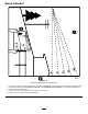
Slope Indicator G011841 Figure 3 This page may be copied for personal use. 1. The maximum slope you can safely operate the machine on is 20 degrees. Use the slope chart to determine the degree of slope of hills before operating. Do not operate this machine on a slope greater than 20 degrees. Fold along the appropriate line to match the recommended slope. 2. Align this edge with a vertical surface, a tree, building, fence pole, etc. 3. Example of how to compare slope with folded edge.
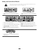
Safety and Instructional Decals Safety decals and instructions are easily visible to the operator and are located near any area of potential danger. Replace any decal that is damaged or lost. 117–4979 93–7321 1. Warning—stay away from moving parts; keep all guards in place. 1. Warning—stay away from moving parts; keep all guards in place. 125–3809 1. Warning—read the Operator’s Manual. 5. Thrown object hazard—keep bystanders away from the machine. 2.
127–4061 1. Cutting blades 4. Hold the handle to start the engine. 2. Fast 5. Release the handle to stop the engine. 3.
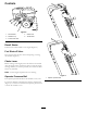
Setup Product Overview Unfolding the Handle 1. Raise the handle to the operating position (Figure 4). Figure 5 1. Operator presence bail 5. Engine On/Off switch 2. Handle 6. Depth control lever 3. Throttle control lever 7. Recoil starter rope 4. Fuel tank Figure 4 2. Slide the oval locking rings down each side of the upper handle over the lower handle (Figure 4), locking the handle sections together.
Controls G023178 Figure 6 1. Recoil starter 2. Sediment cup 4. Choke lever 5. Throttle lever 3. Fuel shut-off valve Recoil Starter Pull the recoil starter handle to start engine (Figure 6). Fuel Shut-off Valve Close the fuel shut-off valve when transporting or storing the machine (Figure 6). Choke Lever Before starting a cold engine, move the choke lever forward. After the engine starts, regulate the choke to keep the engine running smoothly.
Throttle Lever 1 2 Move the control forward to increase the engine speed and rearward to decrease speed; refer to Figure 8. 4 3 g019441 Figure 9 Figure 8 1. Throttle lever Depth Control Lever 1. Depth control lever 3. Hairpin cotter 2. Transport position hole 4. Locking pin Specifications The depth control lever allows you to set the depth of the flail blades in 10 cutting positions along with one position for transportation.
Operation 1 2 3 Note: Determine the left and right sides of the machine from the normal operating position. Checking the Engine Oil Level Service Interval: Before each use or daily 5 1. Stop the engine, disengage the flail blades, turn off the engine switch, and wait for all moving parts to stop. 4 2. Clean around the dipstick (Figure 10) so that dirt cannot fall into the filler hole and damage the engine. g019686 Figure 11 1. Filler tube 2. Dipstick 4. Lower limit 5. Oil drain bolt 3.
Using Stabilizer/Conditioner DANGER In certain conditions, gasoline is extremely flammable and highly explosive. A fire or explosion from gasoline can burn you and others and can damage property. Use a fuel stabilizer/conditioner in the traction unit to provide the following benefits: • Fill the fuel tank outdoors, in an open area, when the engine is cold. Wipe up any gasoline that spills. • Cleans the engine while it runs. • Keeps gasoline fresh during storage of 90 days or less.
Starting and Stopping the Engine Operating the Machine 1. Move the depth control lever to the desired setting. 2. Start the engine. Starting the Engine 1. Turn on the fuel valve. 3. Push down on the handle to raise the front wheels off the ground. 2. Move the choke lever to the left if you are starting a cold engine. 4. Slowly lower the front wheels to the ground, allowing the blades to gradually work into the grass and soil. 3.
Maintenance Recommended Maintenance Schedule(s) Maintenance Service Interval Maintenance Procedure After the first 25 hours • Change the engine oil. Before each use or daily • • • • Check the engine oil level. Clean debris form the machine. Inspect the air cleaner elements. Check the belt tension. If the engine is working but flails seem underpowered, check belt tension • Check the flail blades for wear or damage. • Check for loose fasteners. Every 50 hours • Clean the air filter elements.
Engine Maintenance 10. Clean the foam element in warm, soapy water or in a nonflammable solvent. Note: Do not use gasoline to clean the foam element because it could create a risk of fire or explosion. Servicing the Air Cleaner Service Interval: Before each use or daily—Inspect the air cleaner elements. Every 50 hours—Clean the air filter elements. Clean them more frequently in dusty operating conditions. Every 300 hours/Yearly (whichever comes first)—Replace the paper air cleaner element.
2. Disconnect the wire from the spark plug. 2. Disconnect the wire from the spark plug. 3. Raise the front wheels a few inches off of the ground and place a pan under the drain plug to catch the oil. 3. Move the fuel shut-off valve to the Off position. 4. Remove the sediment cup and O-ring (Figure 17). 4. Remove the drain plug (Figure 16). 1 G019428 2 Figure 16 g020282 Figure 17 1. Drain plug 1. O-ring 5.
Belt Maintenance Checking the Belt Tension Service Interval: Before each use or daily—Check the belt tension. If the engine is working but flails seem underpowered, check belt tension 1. Stop the machine on a level surface, stop the engine, turn off the engine switch, disconnect the spark-plug wire, and raise the flail blades to the highest position. Figure 18 1. Center electrode insulator 2. Side electrode 3. Air gap (not to scale) 2.
Maintaining the Flail Blades Inspecting the Flail Blades Service Interval: Before each use or daily—Check the flail blades for wear or damage. When the flail blades are worn down and are no longer functioning properly; refer to Replacing the Flail Blades (page 18). Important: Perform this procedure when the fuel tank is empty or nearly empty. Tip the machine forward to keep air filter up.
Storage 1. Raise the flail blades, stop the machine, stop the engine, and disconnect the spark plug wire. 2. Remove dirt and grime from the entire machine. Important: You can wash the machine with mild detergent and water. Do not pressure wash the machine. Avoid excessive use of water, especially near the engine. 3. Service the air cleaner; refer to Servicing the Air Cleaner (page 15). 4. Change the engine oil; refer to Changing the Engine Oil (page 15). 5.
5. Check the engine oil level; refer to Checking the Engine Oil Level (page 11). 6. Fill the fuel tank with fresh gasoline; refer to Filling the Fuel Tank (page 12). 7. Connect the wire to the spark plug.
Notes: 21
Notes: 22
Notes: 23
SWS Turf Renovation and Tree Care The Toro Warranty A limited warranty (see warranty periods below) Conditions and Products Covered The Toro Company and its affiliate, Toro Warranty Company, pursuant to an agreement between them, jointly warrant your Toro Products listed below to be free from defects in materials or workmanship. This warranty covers the cost of parts and labor, but you must pay transportation costs.