Form No. 3448-507 Rev A 21in Walk-Behind Aerator Model No. 23515—Serial No. 410050000 and Up Model No. 33515—Serial No. 410020000 and Up Note: Register at www.Toro.com.
on the product. Write the numbers in the space provided. It is a violation of California Public Resource Code Section 4442 or 4443 to use or operate the engine on any forest-covered, brush-covered, or grass-covered land unless the engine is equipped with a spark arrester, as defined in Section 4442, maintained in effective working order or the engine is constructed, equipped, and maintained for the prevention of fire.
Contents Checking Tire-Air Pressure............................... 29 Checking Tine-Drive Chain Tension .................. 29 Adjusting Tine-Drive Chain Tension .................. 30 Belt Maintenance ................................................ 30 Checking Belt Tension ...................................... 30 Adjusting Belt Tension ...................................... 31 Controls System Maintenance ............................. 31 Checking the Traction-Control Handle Adjustment......................
Safety General Safety • This product is capable of injuring hands and feet. Always follow all safety instructions to avoid serious personal injury or death. • Read, understand, and follow the instructions and warnings in this Operator’s Manual and on the machine and attachments before starting the engine. • Be thoroughly familiar with the controls and the proper use of the equipment. Know how to stop the machine and disengage the controls quickly.
Slope Indicator g011841 Figure 3 This page may be copied for personal use. 1. The maximum slope you can safely operate the machine on is 20 degrees. Use the slope chart to determine the degree of slope of hills before operating. Do not operate this machine on a slope greater than 20 degrees. Fold along the appropriate line to match the recommended slope. 2. Align this edge with a vertical surface, a tree, building, fence pole, etc. 3. Example of how to compare slope with folded edge.
Safety and Instructional Decals Safety decals and instructions are easily visible to the operator and are located near any area of potential danger. Replace any decal that is damaged or missing. decal119-0217 119-0217 1. Warning—stop the engine; stay away from moving parts; keep all guards and shields in place. decal121-6151 121-6151 1. Choke–on 3. Continuous variable setting 2. Throttle–fast 4. Throttle–slow Remark masonvn: Please verify if we need Spanish language on this decal.
decal126-0651 126-0651 1. Warning—read the Operator’s Manual. Do not operate this machine unless you are trained. Wear hearing protection. 4. Warning—stay away from moving parts; keep all guards in place. Stop the engine and remove the spark plug before adjusting, servicing, or cleaning. 2. Warning—disengage the tines and stop the engine before leaving the operator’s position. 5. Warning—do not operate when people and pets are in the area. Look behind you when backing up. 3.
decal126-6182 126-6182 1. Cutting/dismemberment hazard of foot, tines—keep feet away 3. Tine transport unlock—1) Pull outward; 2) Rotate rearward from tines when pulling up and locking handle—tines may drop when in transport position if lock is not engaged; read the Operator’s Manual. 2.
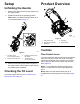
Setup Product Overview Unfolding the Handle 1. Remove the cable tie securing the upper arm to the upper handle. 2. Rotate the handle to the operating position. Note: Make sure that the transport latch pin is in the locked position (Figure 4). g030585 Figure 5 1. Tine-control lever 2. Taction-control handle 3. Handlebar 4. Fuel tank 5. Recoil starter Controls g030543 Figure 4 1. Transport latch pin—Unlocked position 3. Rotate the latch pin over the handle. 2. Push into the lower arm. 4.
Throttle Lever Use the throttle lever to control the engine speed (Figure 5). Apply the engine choke by moving the throttle lever fully forward. g371328 Figure 8 g013076 Figure 6 1. Throttle lever 1. Tine-control lever—raised position 2. Tine-control lever—lowered position Specifications Traction-Control Handle The traction-control lever controls the forward, reverse, and neutral actions of the machine. Refer to Driving the Machine (page 14) for more information.
Operation • To prevent a static charge from igniting the fuel, remove the machine from the truck or trailer and refuel it on the ground, away from all vehicles. If this is not possible, place a portable fuel container on the ground, away from all vehicles, and fill it; then refuel the machine from the fuel container rather than from a fuel-dispenser nozzle. Keep the fuel-dispenser nozzle in contact with the rim of the fuel tank or container opening at all times until fueling is complete.
Important: To reduce starting problems, add fuel stabilizer/conditioner to fresh fuel as directed by the fuel-stabilizer/conditioner manufacturer. Filling the Fuel Tank Fuel tank capacity: 3.8 L (1 US gallon) Important: Do not use fuel additives other than a fuel stabilizer/conditioner. Do not use fuel stabilizers with an alcohol base such as ethanol, methanol, or isopropanol. 1. Clean around the fuel-tank cap and remove the cap from the tank. (Figure 9). g371329 Figure 10 1.
• Always be sure of your footing; keep a firm hold on • Keep bystanders out of the operating area. Keep the handle and walk, never run. small children out of the operating area and under the watchful care of a responsible adult who is not operating the machine. Stop the machine if anyone enters the area. • Be alert, slow down, and use caution when making turns. Look behind and to the side before reversing direction.
g371728 Figure 14 g371726 Figure 12 Driving the Machine • If the engine is warm, move the throttle control to the FAST position (Figure 13). • To move forward, press the control lever forward (Figure 15). The further forward you push it, the faster the machine will travel. A warm engine requires little or no choke to start. • To move in reverse, pull the control lever rearward (Figure 15). The further rearward you pull it, the faster the machine will travel.
Note: The machine aerates in both forward and reverse. 4. When finished, stop the machine and pull the tine control lever rearward and up to lower the rear wheels and lifts the tines out of the ground. Important: Do not drive the machine across pavement or other hard surfaces without first raising the tines. Crossing hard surfaces with the tines lowered will damage the tines. Adding Weight The removable weights are heavy. Use care when lifting them.
Adjusting the Coring Depth A coring depth of 6.35 cm (2-1/2 inches) is recommended, but you can change the depth as follows: 1. Stop engine, wait for all moving parts to stop. 2. Disconnect the wire from the spark plug. 3. Loosen the nuts securing the wheel stop on the right side of the machine (Figure 18). g030543 Figure 19 1. Transport latch pin—unlocked 3. Rotate latch pin over handle. 2. Push into lower arm. 4.
Extending the Handlebar 1. Extend the handlebar (Figure 22). g030542 Figure 20 1. Jam nut 2. Adjuster bolt 7. Tighten the jam nuts and verify that the transport latch pin locks and unlocks. 8. Connect the spark-plug wire to the spark plug. Folding the Handlebar 1. Move the 2 handle-lock rings rearward (Figure 21). g372936 Figure 22 1. Handle-lock rings 2. 2.
unclogging, servicing, cleaning, or storing the machine. • Clean debris from the machine to help prevent 6. Close the fuel-shutoff valve. 7. Secure the machine to the trailer with chains or straps using the tie-down/lift loops (Figure 24). fires. Clean up oil or fuel spills. Hauling Safety • Disconnect the wire from the spark plug before loading the machine for hauling. • Use care when loading or unloading the machine.
Maintenance Important: Refer to your engine owner’s manual for additional maintenance procedures. Note: Download a free copy of the electrical or hydraulic schematic by visiting www.Toro.com and searching for your machine from the Manuals link on the home page. Maintenance Safety • Wear gloves and eye protection when servicing the machine. • Inspect the machine frequently to ensure that it • Never tamper with safety devices.
Maintenance Service Interval Maintenance Procedure Every 250 hours • Replace the fuel filter (more frequently in dusty conditions). Every 300 hours • Replace the air cleaner elements (more frequently in dusty conditions). Yearly or before storage • Touch up chipped paint.
Pre-Maintenance Procedures Installing the Tine Access Cover WARNING Preparing for Maintenance If you operate the machine with the rear access panel removed, someone could be severely injured by contact with the moving tines or by flying debris. CAUTION If you leave the spark pug wire connected, someone could accidently start the engine and seriously injure you or bystanders. Always securely install the rear access panel before operating the machine.
Lubrication Greasing the Tine Shaft Bearings Service Interval: Every 25 hours Every 25 hours Grease Specification: NGLI grade No. 2 multi-purpose g371342 Figure 27 2. Support the front of the machine with a jack stand. 1. Prepare the machine for maintenance; refer to Preparing for Maintenance (page 21) 2. Remove the rear access panel; refer to Removing the Tine Access Cover (page 21). 3.
Engine Maintenance Every 25 hours 1. Prepare the machine for maintenance; refer to Preparing for Maintenance (page 21). 2. Tip up the front of the machine, and support it with jack stands; refer to Raising the Front of the Machine (page 21). Servicing the Air Cleaner Service Interval: Every 25 hours—Clean the foam pre-cleaner (more frequently in dusty conditions). Every 300 hours—Replace the air cleaner elements (more frequently in dusty conditions).
Note: Be careful to prevent dirt and debris from will result. Drain the excess oil until the oil level reaches the upper limit mark on the dipstick. entering the air duct leading to the carburetor. 7. Install the filter element onto the filter base, and install the and air-cleaner cover. 8. Engine Oil Specification Insert the dipstick into the filler neck, and tighten the dipstick cap.
g372562 Figure 32 1. Oil-drain plug 2. Drain port 6. Tip the machine upright again, clean the oil from the frame with a rag. 7. Install the drain plug, and tighten it to 6.9 N∙m (61 in-lb). g372583 Figure 33 1. Oil-filter adapter 4. Adding Oil to the Engine 1.
4. g372583 Figure 35 1. Oil-filter adapter 2. Oil filter 3. Add oil to the engine; refer to Adding Oil to the Engine (page 25) 4. Connect the spark-plug wire, start the engine, and run it for 3 minutes. 5. Stop the engine, wait for all moving parts to stop, and check for oil leakage around the filter. 6. Check the engine-oil level, and add oil as needed; refer to Checking the Engine-Oil Level (page 24).
Fuel System Maintenance Cleaning the Fuel Tank Service Interval: Every 100 hours Emptying the Fuel Tank The fuel filter (screen) element is located inside the fuel tank. 1. Prepare the machine for maintenance; refer to Preparing for Maintenance (page 21). Important: Empty the fuel tank when the engine is cool. 2. Place a drain pan with a 3.8 L (1 US gallon) or greater capacity at the left side of the engine. g372670 Figure 37 3. Close the fuel valve (Figure 42). 1. Capscrew 4.
Installing the Tank 1. Align the tabs of the fuel tank with the plate of the tank-mounting bracket (Figure 39). g372685 Figure 41 4. Squeeze the ends of the hose clamp together and move it over the fitting. 5. Pour fuel into the tank, open the fuel-shutoff valve, and check for leaks. g372671 Note: Repair all fuel leaks. Figure 39 1. Fuel tank 2. 6. 2. Tank-mounting bracket Secure the tank to the flange of the tank-mounting bracket with the 2 flange-head bolts (Figure 40).
Replacing the Fuel Filter Drive System Maintenance Service Interval: Every 250 hours 1. Prepare the machine for maintenance; refer to Preparing for Maintenance (page 21). Important: Replace the fuel filter when the Checking Tire-Air Pressure engine is cool. Service Interval: Every 50 hours 2. Close the fuel-shutoff valve. Air pressure specification: 83-97 kPa (12-14 psi) 3. Place a small drain pan under the fuel filter. 4.
Belt Maintenance Checking Belt Tension Service Interval: Every 25 hours 1. Prepare the machine for maintenance; refer to Preparing for Maintenance (page 21). 2. Raise the front of the machine; refer to Raising the Front of the Machine (page 21). 3. Push on the drive belt midway between the pulleys with 9 kg (20 lb) of force (Figure 46). g023864 Figure 44 1. Flex in the chain 5. Repeat step 4 at the other tine-drive chain. 6. Lower the machine and install the spark-plug wire.
Adjusting Belt Tension 1. Controls System Maintenance Loosen the nut that secures the idler pulley (Figure 46). Checking the Traction-Control Handle Adjustment 1. Prepare the machine for maintenance; refer to Preparing for Maintenance (page 21). 2. Ensure that the tines are raised. 3. Squeeze the traction-control handle to the handlebar until the transaxle is fully engaged. g013125 Figure 47 2. Push the idler pulley to the left to tighten the belt. 3.
Adjusting the Traction-Control Handle Hydraulic System Maintenance 1. Release the traction-control handle. 2. Loosen the top adjustment nut 1 turn and tighten the bottom adjustment nut. Hydraulic System Safety • Seek immediate medical attention if fluid is injected into skin. Injected fluid must be surgically removed within a few hours by a doctor.
Removing the Transaxle Note: Use 2 people or a second hoist to safely remove the transaxle. 1. Remove the locknut (1/4 inch) that secures the fitting of the traction-control cable to the transaxle-control bracket, and separate the cable from the bracket (Figure 50). g372916 Figure 52 1. Belt 3. Belt idler pulley 2. Transaxle pulley g372913 3. Figure 50 1. Fitting (traction-control cable) 3.
g372918 Figure 55 1. Flange locknut (5/16 inch) 3. Transaxle support bracket 2. Carriage bolt (5/16 x 3/4 inch) 4. Bearing bracket 7. While supporting the transaxle, remove the 4 flange locknuts (5/16 inch) that secure the transaxle to the axle mount, and carefully lower the transaxle to the ground (Figure 56). Note: Retain the mounting hardware. g372912 Figure 54 1. Idler sprocket 3. Front tine-drive sprockets 2. Carriage bolt and flange locknut 4. Tine-drive chains 5.
g373038 g373036 Figure 59 Figure 57 1. Drain/fill port 3. 1. Transfer port (expansion tank) 2. Plug Rotate the transaxle over a drain pan, and fully drain oil. Note: Do not remove the tank hose or O-ring unless you need to replace them. 4. Tip the expansion tank over the drain pan, and drain the oil through the transfer port. 5. Insert the vent hose of the expansion tank into the hole in the main transaxle housing (Figure 60). Draining the Expansion Tank 1.
Transaxle Oil Specification Oil type: Toro Premium Hydro Oil Note: Mobil 1 15W50 is an acceptable alternative. Oil quantity: approximately 2.1 L (69.3 fl-oz) Adding Oil to the Transaxle 1. Fill the transaxle with the specified oil through the drain/fill port until the oil level is 13 to 32 mm (1/2 to 1-1/4 inches) below the top of the port (Figure 61). g372917 Figure 62 g373015 1. Axle mount 3. Flange locknuts (3/8 inch) 2. Carriage bolt (3/8 x 2-3/4 inches) 4. Transaxle 3.
g372916 Figure 64 1. Belt 3. Belt idler pulley 2. Transaxle pulley 2. Ensure that the chains are engaged in the rear tine-drive sprockets (Figure 65). g372911 Figure 66 1. Tine-drive sprockets 3. Idler sprocket 2. Tine-drive chains 4. Carriage bolt and flange locknut 4. g372993 Figure 65 Assemble the wheel-drive chain onto the transaxle sprocket and the wheel-drive sprocket, and secure the chain with the connecting link. 1. Rear tine-drive sprocket 3.
Torquing the Transaxle Hardware and Tensioning the Belt and Chains 1. Ensure that the front axle sprocket is aligned with the transaxle sprocket. 2. Torque the 3 flange locknuts (5/16 inch) and 4 carriage bolts as shown in Figure 68. g372913 Figure 69 1. Fitting (traction-control cable) 3. Locknut (1/4 inch) 2. Transaxle-control bracket 2. Secure the fitting to the bracket with the locknut. Checking the Traction-Control Handle 1.
Tine Maintenance Checking the Tines 1. Checking/Replacing Tines At the tine-access panel opening, inspecting the tines for wear or damage (Figure 71). Service Interval: Before each use or daily Preparing to Service the Tines 1. Prepare the machine for maintenance; refer to Preparing for Maintenance (page 21). 2. Ensure that the tines are raised. 3. Remove the tine-access panel; refer to Removing the Tine Access Cover (page 21). 4.
Cleaning Cleaning the Machine Service Interval: Before each use or daily Important: Do not use brackish or reclaimed water to clean the machine. Important: Do not pressure wash the machine. Important: Avoid using excessive amounts of water near the control panel, engine, and transaxle. 1. Park the machine on a level surface, shut off the engine, remove the key, and wait for all moving parts to stop. 2. Thoroughly wash the machine. • Wash the machine with mild detergent and water.
Storage Storage Safety • Shut off the machine and wait for all moving parts to stop before you leave the operator’s position. Disconnect the spark-plug wire, keep it away from the plug to prevent accidental starting, and allow the machine to cool before adjusting, fueling, unclogging, servicing, cleaning, or storing the machine. • Run the engine dry or remove the fuel with a hand pump; never siphon the fuel. If you must drain the fuel tank, do it outdoors.
Troubleshooting Problem The engine does not start. Possible Cause Corrective Action 1. The throttle lever is in the OFF position. 1. Move the throttle lever to the CHOKE position. 2. The spark plug is disconnected. 3. The fuel is turned off. 4. The traction-control handle is not in neutral. 2. Connect the spark plug. 3. Open the fuel valve. 4. Release the traction-control handle so it returns to neutral. The machine vibrates abnormally. 1. There are loose bolts and/or broken parts. 1.
California Proposition 65 Warning Information What is this warning? You may see a product for sale that has a warning label like the following: WARNING: Cancer and Reproductive Harm—www.p65Warnings.ca.gov. What is Prop 65? Prop 65 applies to any company operating in California, selling products in California, or manufacturing products that may be sold in or brought into California.