
Service Manual


T2® / T2-HP
TM
/ T3 HD
TM
19
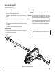
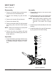
Figure 11, Control Arm
NOTE: Only remove the seal (110) if do-
ing a complete disassembly or if
the seal is worn or damaged.
CONTROL ARM ASSEMBLY
Refer to Figure 11
Disassembly
1. Remove all items previously discussed in
their recommended order.
2. If opening the housing or replacing seals,
remove the oil port plug (13), then; drain oil
from transaxle.
3. Remove the lock nut (49), the washer (46),
the helical compression spring (48), the
spacer (47), the (second) washer (46), and
the plastic washer (45).
4. Remove the Torx head screw (41) and dis-
card.
5. Remove the control arm (42), the (second)
washer (45), the belleville washer (44), and
the set screw (43).
Inspection
1. Inspect all parts for wear or damage. Re-
place if necessary.
13
49
46
46
48
45
47
41
45
42
44
110
Assembly
1. Reassemble all parts in the reverse order
of disassembly.
2. When tightening the fasteners, refer to the
table on page 15 for the required torque
values.
3. Install new Torx head screw (41) and lip seal
(110) from seal kit, if removed.
NOTE: As a general rule, use the low end of
the torque specication on fasteners
when reassembling the unit.
43