
Service Manual


22 T2® / T2-HP
TM
/ T3 HD
TM
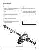
BRAKE ARM & BRAKE ASSEMBLY
Refer to Figure 14
Disassembly
1. Remove all items previously discussed in
their recommended order.
2. Remove the cotter pin (133) and discard.
Mark the orientation of the bias spring (134),
and long screw (127). Remove the brake
arm spring (134), the castle nut (132), and
the washer (131).
3. Remove the brake arm (130), and the brake
compression spring (129).
4. Remove the bolt (128), the bolt (127), and
the spacer (126).
5. Remove the brake yoke (124), the puck
plate (122), and the brake puck (120).
6. Remove the two brake pins (125) from the
brake yoke (124).
7. Remove the brake rotor (121), the inner
puck (120) and the seal (7) and discard.
NOTE: Only remove the seal (7) if damaged
or worn, or if doing a complete disas-
sembly. Refer to “Seal Kit” in the Items
List on page 37.
Inspection
1. Inspect all parts for wear or damage. Re-
place if necessary.
Assembly
1. Reassemble all parts in the reverse order
of disassembly.
2. When tightening the fasteners, refer to the
table on page 15 for the required torque
values.
3. Install new cotter pin (133) and lip seal (7)
from seal kit.
NOTE: As a general rule, use the low end of
the torque specication on fasteners
when reassembling the unit.
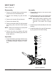
Figure 14, Brake Assembly
121
124
125
125
128
127
126
131
132
133
130
129
120
120
122
134
7