
Service Manual


30 T2® / T2-HP
TM
/ T3 HD
TM
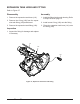
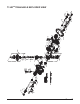
CENTER SECTION, MOTOR SHAFT & MOTOR BLOCK
Figure 23, Center Section, Motor Shaft & Motor Block
Refer to Figure 23
Disassembly
1. Requires removal of all items beginning on
page 17.
2. Remove the center section mounting screws
(22).
3. Remove the center section, the motor shaft
(82) and the bypass plate (23).
4. Remove the motor cylinder block assembly
(75).
5. Remove the motor thrust bearing (79).
Inspection
1. Inspect the races of the thrust bearing (79)
for wear or damage.
2. Inspect the motor shaft for wear or damage.
Replace if necessary.
3. Inspect for scratches on the machined sur-
faces of the center section.
4. Inspect motor cylinder block assembly (75)
per detail on page 31.
5. Inspect the bearing surfaces in the main
housing.
Assembly
1. Reassemble all parts in the reverse order
of disassembly.
2. Apply a light coating of oil to all running
surfaces.
3. Place the thrust bearing assembly (79) into
the main housing. Position so the thick race
will contact the motor block pistons.
4. Insert the motor shaft assembly (82) into the
center section (20).
5. Insert the bypass plate (23) into the center
section.
6. Place the motor cylinder block assembly
(75) onto the motor shaft (82).
7. Insert the center section (20), the motor
shaft (82), the bypass plate (23) and the mo-
tor cylinder block (75) into the main housing
as one assembly.
8. Install the center section screws (22). Refer
to torque chart on page 15.
22
20
79
75
23
83
82
81
80
93
22