Form No. 3397-179 Rev A 21in Walk-Behind Aerator Model No. 23515—Serial No. 315000001 and Up Model No. 33515—Serial No. 315000001 and Up Register at www.Toro.com.
WARNING CALIFORNIA Proposition 65 Warning This product contains a chemical or chemicals known to the State of California to cause cancer, birth defects, or reproductive harm. The engine exhaust from this product contains chemicals known to the State of California to cause cancer, birth defects, or other reproductive harm. This spark ignition system complies with Canadian ICES-002. Figure 1 Important: This engine is not equipped with a spark arrester muffler.
Contents Safety Safety ........................................................................... 3 Safe Operating Practices........................................... 3 Slope Indicator ....................................................... 5 Safety and Instructional Decals ................................. 6 Setup ............................................................................ 9 Unfolding the Handle .............................................. 9 Checking the Oil Level ...................
Operation • Park the aerator on level, hard ground. Never allow untrained personnel to service it. • Never run an engine in an enclosed area. • Only operate in good light, keeping away from holes and • Use jack stands or safety latches to support the machine when working under it. hidden hazards. • Remove the spark-plug wire before making any repairs. • Be sure all drives are in neutral before starting engine.
Slope Indicator G011841 Figure 3 This page may be copied for personal use. 1. The maximum slope you can safely operate the machine on is 20 degrees. Use the slope chart to determine the degree of slope of hills before operating. Do not operate this machine on a slope greater than 20 degrees. Fold along the appropriate line to match the recommended slope. 2. Align this edge with a vertical surface, a tree, building, fence pole, etc. 3. Example of how to compare slope with folded edge.
Safety and Instructional Decals Safety decals and instructions are easily visible to the operator and are located near any area of potential danger. Replace any decal that is damaged or lost. 117–2718 119-0217 121-6150 1. Warning—stop the engine; stay away from moving parts; keep all guards and shields in place. 1. Cutting hazard of hand and foot–stay away from moving parts. 121-6151 1. Choke–on 3. Continuous variable setting 2. Throttle–fast 4. Throttle–slow 116-8699 1.
126-0651 1. Warning—read the Operator’s Manual. Do not operate this machine unless you are trained. Wear hearing protection. 4. Warning—stay away from moving parts; keep all guards in place. Stop the engine and remove the spark plug before adjusting, servicing, or cleaning. 2. Warning—disengage the tines and stop the engine before leaving the operator’s position. 5. Warning—do not operate when people and pets are in the area. Look behind you when backing up. 3.
126-6182 1. Cutting/dismemberment hazard of foot, tines—keep feet away 3. Tine transport unlock—1) Pull outward; 2) Rotate rearward from tines when pulling up and locking handle—tines may drop when in transport position if lock is not engaged; read the Operator’s Manual. 2.
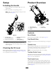
Product Overview Setup Unfolding the Handle 1. Remove the cable tie securing the upper arm to the upper handle. 2. Rotate the handle to the operating position. Note: Make sure that the transport latch pin is in the locked position (Figure 4). Figure 5 1. Tine-control lever 2. Traction-control lever 3. Handle 4. Fuel tank 5. Recoil starter Controls Recoil Starter Figure 4 1. Transport latch pin—Unlocked position 3. Rotate the latch pin over the handle.
Note: Raising the tines may require significant effort if you added extra optional weights to the machine. Operation Note: Make sure that the transport-lock pin is engaged when transporting the machine (see Figure 4). Note: Determine the left and right sides of the machine from the normal operating position. Checking the Engine-Oil Level Service Interval: Before each use or daily The engine crankcase can hold 0.55 L (20 oz) of oil.
Filling the Fuel Tank with Gasoline DANGER When fueling, under certain circumstances, a static charge can develop, igniting the gasoline. A fire or explosion from gasoline can burn you and others and damage property. • Always place gasoline containers on the ground and away from your vehicle before filling. • Do not fill gasoline containers inside a vehicle or on a truck or trailer bed because interior carpets or plastic truck bed liners may insulate the container and slow the loss of any static charge.
4. Install the fuel-tank cap and wipe up any spilled gasoline. 4. Pull the starter handle lightly until you feel resistance, then pull it sharply. Allow the rope to return to the handle slowly. Starting the Engine 5. When the engine starts, move the throttle control to the FAST position. 1. Connect the wire to the spark plug. Note: The throttle setting governs the maximum drive speed of the aerator. 2. Open the fuel valve by turning it in-line with the fuel hose (Figure 9). Stopping the Engine 1.
Driving the Machine Aerating • To move forward, press the control lever forward (Figure 1. Drive the machine to the desired location and stop it. 11). The further forward you push it, the faster the machine will travel. 2. Push the tine control lever down and forward to raise the rear wheels and engage the tines. • To move in reverse, pull the control lever rearward (Figure 11). The further rearward you pull it, the faster the machine will travel.
Adding Weight Adjusting the Coring Depth To ensure that the tines penetrate fully into the soil, you can add weight to the back of the machine. The machine has 3 weight pockets that hold the weights (Figure 13). When placing weights, ensure that you have a balanced load; if using only 1 weight, place it in the center pocket, and if using 2 weights, place them in the side pockets. A coring depth of 6.35 cm (2-1/2 inches) is recommended, but you can change the depth as follows: 1.
Adjusting the Tine-Control Lever 1. Stop engine, wait for all moving parts to stop. 2. Disconnect the wire from the spark plug. 3. Raise the tines to the transport position. 4. Attempt to lock the transport latch pin into the lower arm (see Figure 15). Figure 16 1. Jam nut 2. Adjuster bolt 7. Tighten the jam nuts and verify that the transport latch pin can be locked and unlocked. Transporting the Machine Important: Do not operate or drive the machine on roadways. 1.
Maintenance Recommended Maintenance Schedule(s) Maintenance Service Interval Maintenance Procedure After the first 5 hours • Change the engine oil. Before each use or daily • • • • • • Check the engine oil level. Check the condition and tension of the tine-drive chains. Check the condition of the front drive chains. Check the condition of the drive chain sprockets. Lubricate the tine-drive chains. Check the condition of the coring tines and replace any that are damaged or excessively worn.
Premaintenance Procedures Tipping the Machine If you need to work on the underside of the machine, you can tip it backward (Figure 18). Do not tip the machine forward or you will fill the air cleaner with gasoline. Secure the machine with a jack stand before working under it. Accessing the Tines The machine has a rear access panel that you can remove to access and maintain the tines (Figure 17). 1 g017586 Figure 18 1.
Lubrication CAUTION If you do not securely block up the front of the machine, the machine could fall on you during service, injuring you. Greasing the Tine Shaft Bearings Ensure that you place a jack-stand or block under the front of the machine to hold it up securely. Service Interval: Every 25 hours Every 25 hours 1. Raise the tines, stop the machine, stop the engine, and disconnect the spark-plug wire. Important: Do not raise the rear of the machine.
Engine Maintenance 7. Install the foam pre-cleaner onto the paper air filter. Note: Use a new paper air filter if you discarded the old one. Servicing the Air Cleaner 8. Install the air filter assembly and cover. Service Interval: Every 25 hours—Clean the foam pre-cleaner (more frequently in dusty conditions). Changing the Engine Oil Every 300 hours—Replace the air cleaner elements (more frequently in dusty conditions).
Changing the Oil Filter Service Interval: Every 100 hours 1. Drain the engine oil; refer to Changing the Engine Oil (page 19). 2. Place a rag under the oil filter (Figure 22) to catch any oil that may leak out as you remove the filter. 1 3. Remove the oil filter. 2 4. Use your finger to coat the gasket on the new filter with oil (Figure 23). g017582 Figure 22 1. Oil-drain plug 2. Oil filter Figure 23 7.
Servicing the Spark Plug Checking the Spark Arrester (if equipped) Service Interval: Every 100 hours—Inspect, clean, and adjust the spark plug; replace it if necessary. Service Interval: Every 50 hours Every 200 hours—Replace the spark plug. WARNING 1. Stop the engine and wait for all moving parts to stop. Hot exhaust system components may ignite gasoline vapors even after the engine is stopped. Hot particles exhausted during engine operation may ignite flammable materials.
Replacing the Fuel Filter Fuel System Maintenance Service Interval: Every 250 hours 1. Stop the engine and wait for it to cool down. Emptying the Fuel Tank and Cleaning the Fuel Filter 2. Disconnect the wire from the spark plug. Service Interval: Every 100 hours 3. Close the fuel valve. The fuel filter (screen) element is located inside the fuel tank. 4. Clamp off the fuel line on either side of the fuel filter (Figure 25) to prevent fuel from leaking out when you remove the filter.
Drive System Maintenance 3. Pull down on each chain near the opening in the frame with 9 kg (20 lb) of force (Figure 27). If a chain flexes more than 3 mm (1/8 inch), tighten it as follows: Checking the Tire Pressure Service Interval: Every 50 hours Maintain the air pressure in the tires as specified. Check the tires when they are cold to get the most accurate reading. Pressure: 83-97 kPa (12-14 psi) 1 Figure 27 1. Flex in the chain A.
Belt Maintenance Controls System Maintenance Checking the Hydrostatic Drive Belt Adjusting the Self-Propel Drive Service Interval: Every 25 hours 1. Raise the tines, stop the machine, stop the engine, and disconnect the spark-plug wire. 1. Raise the tines, stop the machine, stop the engine, and disconnect the spark-plug wire. 2. Squeeze the self-propel bail to the handle until the transmission is fully stroked. 2.
Hydraulic System Maintenance Changing the Hydraulic Transmission Fluid B. Remove the drive belt from the transmission pulley by loosening the nut on the idler pulley. C. Remove and retain the connecting link from the front-axle-chain sprocket and remove the chain. D. Loosen the drive chain idler sprockets on each side of the machine. E. Remove and retain the connecting link from the drive chains, and remove the drive chain from the transmission sprockets. Service Interval: Every 100 hours 1.
D. Tine Maintenance Install the chain on the front axle sprocket. Ensure that the front axle sprocket is aligned with the sprocket on the transmission. E. Tighten the 7 transmission mounting bolts. Checking/Replacing Tines F. Tension the transmission belt; refer to Checking the Hydrostatic Drive Belt (page 24). Service Interval: Before each use or daily G. Tension the tine-drive chains; refer to (page ). 1. Raise the tines, stop the machine, stop the engine, and disconnect the spark-plug wire. H.
Storage 1. Raise the tines, stop the machine, stop the engine, and disconnect the spark-plug wire. 2. Remove dirt and grime from the entire machine. Important: You can wash the machine with mild detergent and water. Do not pressure wash the machine. Avoid excessive use of water, especially near the engine and hydrostatic drive. 3. Service the air cleaner; refer to Servicing the Air Cleaner (page 19). 4. Grease the chains and floating tine assemblies; refer to Lubrication (page 18). 5.
Troubleshooting Problem The engine does not start. Possible Cause Corrective Action 1. The throttle lever is in the OFF position. 1. Move the throttle lever to the CHOKE position. 2. The spark plug is disconnected. 3. The fuel is turned off. 4. The traction lever is not in neutral. 2. Connect the spark plug. 3. Open the fuel valve. 4. Release the traction lever so it returns to neutral. The machine vibrates abnormally. 1. There are loose bolts and/or broken parts. 1.
Notes: 29
Notes: 30
Notes: 31
The Toro Warranty A limited warranty (see warranty periods below) Conditions and Products Covered The Toro Company and its affiliate, Toro Warranty Company, pursuant to an agreement between them, jointly warrant your Toro Products listed below to be free from defects in materials or workmanship. This warranty covers the cost of parts and labor, but you must pay transportation costs.