Form No. 3379-664 Rev B 21in Walk-Behind Aerator Model No. 23515—Serial No. 314000001 and Up Model No. 33515—Serial No. 314000001 and Up Register at www.Toro.com.
This spark ignition system complies with Canadian ICES-002. Important: This engine is not equipped with a spark arrester muffler. It is a violation of California Public Resource Code Section 4442 to use or operate the engine on any forest-covered, brush-covered, or grass-covered land. Other states or federal areas may have similar laws.
Safety Adjusting the Handle .......................................... 9 Checking the Engine Oil Level .......................... 10 Filling the Fuel Tank with Gasoline .....................11 Starting the Engine ........................................... 12 Stopping the Engine ......................................... 12 Driving the Machine .......................................... 12 Aerating ............................................................ 13 Adding Weight .................................
Maintenance and Storage – Never refuel or drain the aerator indoors. • Check that the controls, safety switches, and • Wait for all movement to stop before adjusting, shields are attached and functioning properly. Do not operate unless they are functioning properly. cleaning, or repairing. Raise the tines, stop the machine, stop the engine, and disconnect the spark plug wire. Operation • Clean grass and debris from the tines, drives, mufflers, and engine to help prevent fires.
Slope Indicator g011841 Figure 3 This page may be copied for personal use. 1. The maximum slope you can safely operate the machine on is 20 degrees. Use the slope chart to determine the degree of slope of hills before operating. Do not operate this machine on a slope greater than 20 degrees. Fold along the appropriate line to match the recommended slope. 2. Align this edge with a vertical surface, a tree, building, fence pole, etc. 3. Example of how to compare slope with folded edge.
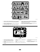
Safety and Instructional Decals Safety decals and instructions are easily visible to the operator and are located near any area of potential danger. Replace any decal that is damaged or lost. decal121-6151 121-6151 decal121-6150 121-6150 1. Cutting hazard of hand and foot–stay away from moving parts. 1. Choke–on 3. Continuous variable setting 2. Throttle–fast 4. Throttle–slow decal119-0217 119-0217 1. Warning—stop the engine; stay away from moving parts; keep all guards and shields in place.
decal126-0651 126-0651 1. Warning—read the Operator’s Manual. Do not operate this machine unless you are trained. Wear hearing protection. 4. Warning—stay away from moving parts; keep all guards in place. Stop the engine and remove the spark plug before adjusting, servicing, or cleaning. 2. Warning—disengage the tines and stop the engine before leaving the operator’s position. 5. Warning—do not operate when people and pets are in the area. Look behind you when backing up. 3.
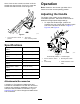
Product Overview Setup Unfolding the Handle 1. Raise the handle to the operating position. g023762 Figure 5 g017578 1. Tine-control lever 2. Traction-control lever 3. Handle Figure 4 2. Slide the oval locking rings down each side of the upper handle over the lower handle, locking the handle sections together. 4. Fuel tank 5. Recoil starter 6. Throttle lever Controls Recoil Starter Checking the Oil Level Pull the recoil starter handle to start engine (Figure 5).
Operation tines. Push the tine control lever down to lift the wheels and drop the tines. Pull it up to lower the wheels and raise the tines out of the ground. Note: Determine the left and right sides of the machine from the normal operating position. Adjusting the Handle The height of the handle can be adjusted for comfortable operation. Stand behind the handle to determine the appropriate height settings. 1.
detergent oil that has the American Petroleum Institute (API) service classification SH, SJ, Sl or higher. Note: When the crankcase is empty, pour about 3/4 of the crankcase capacity of oil in the crankcase, then follow the procedure in this section. 1. Move the machine to a level surface. 2. Clean around the dipstick (Figure 10). g023052 Figure 8 Middle handle position 1. Trunnion bracket—bottom hole 2. Lift link straps 3. Mounting bolt location 4.
Filling the Fuel Tank with Gasoline DANGER When fueling, under certain circumstances, a static charge can develop, igniting the gasoline. A fire or explosion from gasoline can burn you and others and damage property. • Always place gasoline containers on the ground and away from your vehicle before filling. • Do not fill gasoline containers inside a vehicle or on a truck or trailer bed because interior carpets or plastic truck bed liners may insulate the container and slow the loss of any static charge.
Important: Do not fill the tank more than 6 mm (1/4 inch) from the top of the tank because the gasoline must have room to expand. 4. Install the fuel tank cap and wipe up any spilled gasoline. Starting the Engine 1. Connect the wire to the spark plug. 2. Open the fuel valve by turn it in-line with the fuel hose (Figure 12). g016910 Figure 13 1. Throttle control 4. Pull the starter handle lightly until you feel resistance, then pull it sharply. Allow the rope to return to the handle slowly. 5.
• To make zero turns, pull up on the tine ground engagement lever and raise the tines. Important: Do not make a zero turn when the tines are down. Turning with the tines down will result in turf tearing. • To stop, release the control lever (Figure 14). g013076 Figure 15 1. Tine control lever—tines disengaged from the ground 2. Tine control lever—tines engaged into the ground 3. Drive the machine to aerate the desired area. Note: The machine with aerate in both forward and reverse. 4.
Note: To ensure that the tines penetrate fully into the soil, weights can be added to the back of the machine. The machine has three weight pockets that hold the weights. When placing weight, ensure that the load is balanced; if using only one weight, place it in the center pocket and if using two, place them in the side pockets. Note: The removable weights are heavy. Use care when lifting them. Make sure that you can hold them securely before lifting them.
g023657 Figure 19 1. Handle pivot bolt 4. Lift link strap ball joint 2. Lower ball joint bolt 5. Adjust here g023658 Figure 20 3. 1/4 inch (6 mm) 6. Slide the oval locking rings upward on the handle and fold the handle towards the engine. 7. The ball joint on the tine-control lever should contact the handle firmly; if not, proceed to step 8. 1. Handle 2. Self-propel drive bail 3. 4. 5. 6. 15 Tine-control lever Jam nut Link rod Ball joint contacts handle 8.
Securing the Machine for Transport When transporting the machine on a trailer, always use the following procedure: Important: Do not operate or drive the machine on roadways. 1. Drive the machine onto that trailer, stop the machine, stop the engine, turn off the fuel valve, and disconnect the spark plug wire. Important: If you do not turn off the fuel valve, the engine may flood during transport. 2. Secure the machine to the trailer with chains or straps using the tie-down/lift loops (Figure 5).
Maintenance Recommended Maintenance Schedule(s) Maintenance Service Interval Maintenance Procedure After the first 5 hours • Change the engine oil. Before each use or daily • • • • • • Check the engine oil level. Check the condition and tension of the tine drive chains. Check the condition of the front drive chains. Check the condition of the drive chain sprockets. Lubricate the tine drive chains. Check the condition of the coring tines and replace any that are damaged or excessively worn.
Pre-Maintenance Procedures Accessing the Tines The machine has a rear access panel that you can remove to access and maintain the tines (Figure 21). g017586 Figure 22 1. Jack stand WARNING Mechanical or hydraulic jacks may fail to support machine and cause a serious injury. • Use jack stands when supporting machine. • Do not use hydraulic jacks. g023846 Figure 21 1.
Lubrication 2. Greasing the Tine Shaft Bearings Raise the front of the machine to gain access to the chains (Figure 22) and block it in place. CAUTION If you do not securely block the up the front of the machine, the machine could fall on you during service, injuring you. Service Interval: Every 25 hours Every 25 hours 1. Raise the tines, stop the machine, stop the engine, and disconnect the spark plug wire.
8. Engine Maintenance Wipe up any oil that spilled and lower the machine to the ground when finished. Servicing the Air Cleaner Service Interval: Every 25 hours—Clean the foam pre-cleaner (more frequently in dusty conditions). Every 300 hours—Replace the air cleaner elements (more frequently in dusty conditions). Important: Do not operate the engine without the air filter assembly; extreme engine damage may occur. 1. Stop the engine and wait for all moving parts to stop. 2.
6. Wipe dirt from the base and the cover with a moist rag. Note: Be careful to prevent dirt and debris from entering the air duct leading to the carburetor. 7. Install the foam pre-cleaner onto the paper air filter. Note: Use a new paper air filter if you discarded the old one. 8. Install the air filter assembly and cover. Changing the Engine Oil Service Interval: After the first 5 hours Every 50 hours Oil Capacity With oil filter 0.85 L (29 ounces) Without oil filter 0.
because grit entering the cylinder can damage the engine. 5. Set the gap on the plug to 0.76 mm (0.030 inch) (Figure 28). g002805 Figure 27 r:\g000533 5. Install the new filter and hand tighten it 2/3 turn only. 6. Insert the dipstick into the filler neck and rotate the cap clockwise until it is tight. 7. Slowly pour oil into the oil fill tube, periodically checking the level with the dipstick, until the dipstick indicates that the engine is full. Do not overfill. (Max. fill: 0.
4. Fuel System Maintenance If you observe plugging of the screen, remove the spark arrester, shake the loose particles out of it, and clean the screen with a wire brush (soak in solvent if necessary). Replace the spark arrester when finished. Emptying the Fuel Tank and Cleaning the Fuel Filter Service Interval: Every 100 hours The fuel filter (screen) element is located inside the fuel tank. 1. Stop the engine and wait for it to cool down. Note: Drain gasoline for a cold engine only. 2.
Drive System Maintenance Checking the Tire Pressure Service Interval: Every 50 hours Maintain the air pressure in the tires as specified. Check the tires when they are cold to get the most accurate reading. Pressure: 83-97 kPa (12-14 psi) g017588 Figure 29 1. Fuel filter 2. Fuel valve 5. Squeeze the ends of the hose clamps together and slide them away from the filter (Figure 29). 6. Remove the filter from the fuel lines. 7.
Belt Maintenance Checking the Hydrostatic Drive Belt Service Interval: Every 25 hours g023864 1. Raise the tines, stop the machine, stop the engine, and disconnect the spark plug wire. 2. Raise the front of the machine to gain access to the pump drive belt and block it in place. Figure 31 1. Flex in the chain A. CAUTION If you do not securely block the up the front of the machine, the machine could fall on you during service, injuring you.
Controls System Maintenance Hydraulic System Maintenance Adjusting the Self-Propel Drive Changing the Hydraulic Transmission Fluid 1. Raise the tines, stop the machine, stop the engine, and disconnect the spark plug wire. 2. Squeeze the self-propel bail to the handle until the transmission is fully stroked. Service Interval: Every 100 hours If the bail contacts the handle, release the bail. Loosen the top adjustment nut one turn and tighten the bottom adjustment nut. Squeeze the bail to the handle.
C. Remove and retain the connecting link from the front axle chain sprocket, and remove the chain. D. Loosen the drive chain idler sprockets on each side of the unit. Remove and retain the connecting link from the drive chains, and remove the drive chain from the transmission sprockets. E. Support the transmission, remove and retain its mounting hardware, and carefully lower the transmission to the ground. 6. Carefully clean the area around the expansion tank and oil-fill port.
Tine Maintenance Storage Checking/Replacing Tines 1. Raise the tines, stop the machine, stop the engine, and disconnect the spark plug wire. Service Interval: Before each use or daily 2. Remove dirt and grime from the entire machine. 1. Raise the tines, stop the machine, stop the engine, and disconnect the spark plug wire. 2. Remove the rear access panel; refer to Accessing the Tines (page 18) 3. Manually rotate the tines on the shaft, inspecting them for wear or damage. 3.
Troubleshooting Problem Engine will not start. Possible Cause Corrective Action 1. The throttle lever is in the Off position. 1. Move the throttle lever tot he Choke position. 2. The spark plug is disconnected. 3. The fuel is turned off. 4. The traction lever is not in neutral. 2. Connect the spark plug. 3. Open the fuel valve. 4. Release the traction lever so it returns to neutral. The machine vibrates abnormally. 1. Loose bolts and/or broken parts. 1. Stop the machine and engine immediately.
Notes:
Notes:
The Toro Warranty A limited warranty (see warranty periods below) SWS Turf Renovation and Tree Care Conditions and Products Covered Owner Responsibilities The Toro Company and its affiliate, Toro Warranty Company, pursuant to an agreement between them, jointly warrant your Toro Products listed below to be free from defects in materials or workmanship. You must maintain your Toro Product by following the maintenance procedures described in the Operator’s Manual.