Form No. 3365-260 Rev C 21-inch Walk-Behind Aerator Model No. 23515—Serial No. 312000001 and Up Model No. 33515—Serial No. 312000001 and Up Register at www.Toro.com.
This spark ignition system complies with Canadian ICES-002. Important: This engine is not equipped with a spark arrester muffler. It is a violation of California Public Resource Code Section 4442 to use or operate the engine on any forest-covered, brush-covered, or grass-covered land. Other states or federal areas may have similar laws.
Contents Safety Safety ....................................................................... 3 Safe Operating Practices.................................... 3 Slope Indicator ................................................... 5 Safety and Instructional Decals .......................... 6 Setup ........................................................................ 7 Unfolding the Handle .......................................... 7 Checking the Oil Level ........................................
• Do not make sudden turns or rapid speed changes. – Never refuel or drain the aerator indoors. • Check that the controls, safety switches, and • Reduce speed and use extreme caution on slopes. shields are attached and functioning properly. Do not operate unless they are functioning properly. • Remove or mark obstacles such as rocks, tree limbs, etc. from the operating area. Tall grass can hide obstacles. Operation • Never run an engine in an enclosed area.
Slope Indicator g011841 Figure 3 This page may be copied for personal use. 1. The maximum slope you can safely operate the machine on is 20 degrees. Use the slope chart to determine the degree of slope of hills before operating. Do not operate this machine on a slope greater than 20 degrees. Fold along the appropriate line to match the recommended slope. 2. Align this edge with a vertical surface, a tree, building, fence pole, etc. 3. Example of how to compare slope with folded edge.
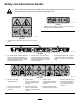
Safety and Instructional Decals Safety decals and instructions are easily visible to the operator and are located near any area of potential danger. Replace any decal that is damaged or lost. decal119-0217 119-0217 1. Warning—stop the engine; stay away from moving parts; keep all guards and shields in place. decal121-6150 121-6150 1. Cutting hazard of hand and foot–stay away from moving parts. decal121-2008 121-2008 1. To start the engine, read the Operator’s 2.
Product Overview Setup Unfolding the Handle 1. Raise the handle to the operating position. g017579 Figure 5 1. Fuel shut-off valve 2. Air cleaner 3. Spark plug wire g017578 Figure 4 2. Slide the oval locking rings down each side of the upper handle over the lower handle, locking the handle sections together. 9. Traction control lever 10. Throttle lever 11. Tine control lever 4. Engine 12. Oval handle locking ring 5. Recoil starter 13. Coring depth, wheel stop 6. Fuel tank 14.
Tine Control Lever Operation The tine control lever lifts the rear wheels, causing the rear of the machine to be supported on the aerating tines. Push the tine control lever down to lift the wheels and drop the tines. Pull it up to lower the wheels and raise the tines out of the ground. Note: Determine the left and right sides of the machine from the normal operating position. Checking the Engine Oil Level Service Interval: Before each use or daily The engine crankcase can hold 20 ounces (0.
8. Insert the dipstick into the filler neck and rotate the cap clockwise until it is tight. DANGER When fueling, under certain circumstances, a static charge can develop, igniting the gasoline. A fire or explosion from gasoline can burn you and others and damage property. Filling the Fuel Tank with Gasoline Fuel tank capacity: 3.76 L (0.99 US gallon) • Always place gasoline containers on the ground and away from your vehicle before filling.
g017581 Figure 8 g017588 Figure 9 1. Fuel tank cap 2. Remove the cap from the tank. 3. Fill the fuel tank with unleaded gasoline to within 1/4 to 1/2 inch (6 to 13 mm) from the top of the tank. Do not fill into the filler neck. 1. Fuel filter 3. 2. Fuel valve—off position Move the throttle control all the way forward to the Choke position (Figure 9). Note: Do not use the choke when the engine is warm.
Stopping the Engine 1. 2. Note: If your machine is moving too slowly and not properly aerating, see Adjusting the Machine Ground Speed (page 21) Release the traction control lever and allow it to return to neutral. Move the throttle lever all the way rearward to stop the engine. Aerating Driving the Machine • To move forward, press the control lever forward • 1. Drive the machine to the desired location and stop it. 2.
Securing the Machine for Transport When transporting the machine on a trailer, always use the following procedure: Important: Do not operate or drive the machine on roadways. 1. Drive the machine onto that trailer, stop the machine, stop the engine, turn off the fuel valve, and disconnect the spark plug wire. Important: If you do not turn off the fuel valve, the engine may flood during transport. 2. g017584 Secure the machine to the trailer with chains or straps using the tie-down/lift loops (Figure 5).
Maintenance Recommended Maintenance Schedule(s) Maintenance Service Interval Maintenance Procedure After the first 8 hours • Change the engine oil. After the first 10 hours • Check the tension of the drive chains. After the first 25 hours • Check the tension of the hydrostatic drive belt. Before each use or daily • • • • Check the engine oil level. Lubricate the pivot arms. Check the tire pressure. Check the condition of the coring tines and replace any that are damaged or excessively worn.
WARNING Mechanical or hydraulic jacks may fail to support machine and cause a serious injury. • Use jack stands when supporting machine. • Do not use hydraulic jacks. g017585 Figure 15 WARNING If you operate the machine with the rear access panel removed, some one could be severely injured by contact with the moving tines or by flying debris. Always securely install the rear access panel before operating the machine.
Lubrication CAUTION If you do not securely block the up the front of the machine, the machine could fall on you during service, injuring you. Greasing the Center Tines Service Interval: Before each use or daily 1. Raise the tines, stop the machine, stop the engine, and disconnect the spark plug wire. Ensure that you place a jack-stand or block under the front of the machine to hold it up securely. 2.
Engine Maintenance 6. Wipe dirt from the base and the cover with a moist rag. Note: Be careful to prevent dirt and debris from Servicing the Air Cleaner entering the air duct leading to the carburetor. 7. Service Interval: Every 25 hours—Clean the foam pre-cleaner (more frequently in dusty conditions). Install the foam pre-cleaner onto the paper air filter. Note: Use a new paper air filter if you discarded Every 300 hours—Replace the paper air filter (more frequently in dusty conditions).
g002805 Figure 22 g017582 Figure 21 1. Oil drain plug 5. Install the new filter and hand tighten it 2/3 turn only. 6. Insert the dipstick into the filler neck and rotate the cap clockwise until it is tight. 7. Slowly pour oil into the oil fill tube, periodically checking the level with the dipstick, until the dipstick indicates that the engine is full. Do not overfill. (Max. fill: 20 oz. (0.55 l), type: SAE 30W detergent oil with an API service classification of SH, SJ, SL, or higher.) 2.
Fuel System Maintenance because grit entering the cylinder can damage the engine. 5. Set the gap on the plug to 0.030 inch (0.76 mm) (Figure 23). Replacing the Fuel Filter Service Interval: Every 250 hours 1. Stop the engine and wait for it to cool down. Important: Drain gasoline from a cold engine only. r:\g000533 Figure 23 2. Disconnect the wire from the spark plug. 3. Close the fuel valve. 4.
Drive System Maintenance (Figure 26). If a chain contacts the bottom of the opening in the frame, tighten it as follows: Checking the Tire Pressure Service Interval: Before each use or daily Maintain the air pressure in the tires as specified. Check the tires when they are cold to get the most accurate reading. Pressure: 46 psi (317 kPa) g013126 Figure 26 1. Flex in the chain A. 2. Bottom of the frame opening Loosen the nut securing the idler sprocket of the chain you are tensioning (Figure 27).
Belt Maintenance C. Checking the Hydrostatic Drive Belt Service Interval: After the first 25 hours Every 50 hours 1. Raise the tines, stop the machine, stop the engine, and disconnect the spark plug wire. 2. Raise the front of the machine to gain access to the pump drive belt and block it in place. CAUTION If you do not securely block the up the front of the machine, the machine could fall on you during service, injuring you.
Controls System Maintenance • Loosen and remove the linkage adjustment from the bracket (Figure 31). • Move the lower nut to the end of the thread (Figure 31). Note: Ensure that the bail will reach the Adjusting the Machine Ground Speed 1. handle after the transmission is engaged. Loosen the 2 bolts securing the cable attachment bracket and slide it as far as possible to the left then tighten the 2 bolts (Figure 29). g020483 Figure 29 g020485 1. Bolts 2. Cable attachment bracket Figure 31 1.
Tine Maintenance Checking/Replacing Tines Service Interval: Before each use or daily g020486 Figure 32 1. Nuts 22 1. Raise the tines, stop the machine, stop the engine, and disconnect the spark plug wire. 2. Remove the rear access panel; refer to Accessing the Tines (page 13) 3. Manually rotate the tines on the shaft, inspecting them for wear or damage. 4. If any are damaged or broken, remove the nut and bolt securing the tine to the tine assembly (Figure 33).
Storage 1. Raise the tines, stop the machine, stop the engine, and disconnect the spark plug wire. 2. Remove dirt and grime from the entire machine. Important: You can wash the machine with mild detergent and water. Do not pressure wash the machine. Avoid excessive use of water, especially near the engine and hydrostatic drive. g013128 Figure 33 1. Tine assembly 3. Bolt and nut 3. Service the air cleaner; refer to Servicing the Air Cleaner (page 16). 4.
Troubleshooting Problem Engine will not start. Possible Cause Corrective Action 1. The throttle lever is in the Off position. 1. Move the throttle lever tot he Choke position. 2. The spark plug is disconnected. 3. The fuel is turned off. 4. The traction lever is not in neutral. 2. Connect the spark plug. 3. Open the fuel valve. 4. Release the traction lever so it returns to neutral. The machine vibrates abnormally. 1. Loose bolts and/or broken parts. 1. Stop the mchine and engine immediately.
Notes:
Notes:
Notes:
Toro Compact Utility Equipment Warranty A One-Year Limited Warranty CUE Products Conditions and Products Covered Items and Conditions Not Covered The Toro® Company and its affiliate, Toro Warranty Company, pursuant to an agreement between them, jointly warrant your Toro Compact Utility Equipment (“Product”) to be free from defects in materials or workmanship.