Form No. 3399-188 Rev B Walk-Behind Rotary Broom Model No. 23740—Serial No. 316000001 and Up Register at www.Toro.com.
Replacement engine owner’s manuals may be ordered through the engine manufacturer. WARNING CALIFORNIA Proposition 65 Warning The engine exhaust from this product contains chemicals known to the State of California to cause cancer, birth defects, or other reproductive harm. g019350 Figure 1 1. Model and serial-number location Introduction Important: It is a violation of California Public Model No.
Contents Safety ....................................................................... 4 Training .............................................................. 4 Preparation......................................................... 4 Operation............................................................ 4 Clearing a Clogged Broom.................................. 5 Maintenance and Storage................................... 5 Slope Indicator ...................................................
Safety Read and understand the contents of this manual before the engine is ever started. This is the safety-alert symbol. It is used to alert you to potential personal injury hazards. Obey all safety messages that follow this symbol to avoid possible injury or death. • Improperly using or maintaining this machine could result in injury or death. To reduce this potential, comply with the following safety instructions. Operation • Never allow children to operate the machine.
• Maintain or replace the safety and instruction stopped. Disconnect the spark-plug wire, and keep the wire away from the plug to prevent accidental starting. labels, as necessary. • When operating in snow conditions, run the • Disengage the power to the rotary broom when machine for a few minutes after throwing snow to prevent freeze up of the broom and housing. the machine is transported or not in use.
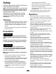
Slope Indicator g011841 Figure 3 1. The maximum slope you can safely operate the machine on is 10°. Use the slope indicator to determine the degree of slope of hills before operating. Do not operate this machine on a slope greater than 10°. Fold along the appropriate line to match the recommended slope. 2. Align this edge with a vertical surface, a tree, building, fence pole, etc. 3. Example of how to compare slope with folded edge.
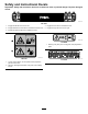
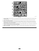
Safety and Instructional Decals Important: Safety and instruction decals are located near areas of potential danger. Replace damaged decals. decal126-0017 126–0017 1. Engage the left-turn lever to turn left. 4. Engage the PTO lever to activate the PTO. 2. Engage the traction-control lever to activate the traction drive. 5. Engage the right-turn lever to turn right. 3. Engage the broom-angle lever to adjust the broom. decal112-9028 112-9028 1.
decal116-7370 116-7370 1. Warning—Read the Operator’s Manual. Do not operate this machine unless you are trained. Stay away from moving parts; keep all guards in place. 2. Thrown object hazard—Do not operate when people and pets are in the area; pick up objects that could be thrown by broom. 3. Warning—Wear hearing protection. 4. Warning—shut off the engine and disconnect the spark plug before adjusting, servicing, or cleaning machine and attachments.
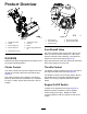
Product Overview g023785 Figure 5 g030588 Figure 4 1. Wheel-clutch lever 2. Handle 6. Traction-drive lever 7. Fuel cap 3. Broom-angle lever 8. Broom 4. Broom-drive lever 9. Broom-height-adjustment pin 1. Choke control 4. Engine-recoil handle 2. Fuel-shutoff valve 5. Engine On/Off switch 3. Throttle control Fuel-Shutoff Valve 5.
Wheel-Clutch Levers Speed-Selector Lever The wheel-clutch levers are located below the right and left handles. The speed-selection lever is located on the main console panel (Figure 6). The wheel clutch levers allow the drive to momentarily disengage to 1 or both wheels with the traction-drive lever squeezed. This allows for easier turning and maneuvering the machine (Figure 6). The speed selector has 6 forward and 2 reverse settings.
Operation DANGER When fueling, under certain circumstances, a static charge can develop, igniting the gasoline. A fire or explosion from gasoline can burn you and others and damage property. Fueling the Machine Fuel tank capacity: 4.1 L (1.0 US gallon) • For best results, use only clean, fresh (less than 30 days old), unleaded gasoline with an octane rating of 87 or higher ((R+M)/2 rating method). • Always place gasoline containers on the ground and away from your vehicle before filling.
Opening the Fuel-Shutoff Valve Important: Do not fill the tank more than 6 mm (1/4 inch) from the top of the tank to allow the gasoline room to expand. 4. Move the fuel-shutoff valve located below the choke, to the right to turn on fuel (Figure 9). Install the fuel-tank cap and wipe up any spilled gasoline (Figure 7).
Driving Forward engine, leave the choke lever in the OFF position (Figure 9). 3. Place the throttle midway between the SLOW and FAST positions located on rear, right side of the engine (Figure 10). 4. Slowly pull the engine-recoil handle until you feel resistance and then stop (Figure 10). 1. Place the speed selector lever to the desired forward position, making sure that it locks in the notch (Figure 11). Note: Allow the recoil handle to return and then sharply pull it straight out.
allows you to maneuver and transport the machine more easily when the engine is not running. Operating the Broom DANGER When the machine is in operation, contact with rotating or moving parts will severely injure hands and feet. g001307 Figure 13 Note: Similarly, squeezing the left wheel-clutch • Before adjusting, cleaning, inspecting, troubleshooting, or repairing the machine, shut off the engine and wait for all moving parts to stop.
Checking the Sweeping Path CAUTION When the broom is engaged, it may drive the unit in the reverse direction. If the broom height is adjusted too low, the machine may move more forcefully in the reverse direction, causing injury and/or property damage. A broom sweeps with the tips of its bristles. When you apply too much downward pressure, the broom no longer uses its tips; the broom is now working with the sides of the bristles.
Adjusting the Broom Height Adjusting the Broom Side 1. Drive to a flat, dusty area and stop the machine. Angle 2. 3. 4. 5. Disengage the broom and shut off the engine. Wait for all moving parts to stop before leaving the operating position. Shut off the engine On/Off switch to the OFF position. To adjust the broom height, remove and retain the pin from the adjuster sleeve and wheel tube of the caster (Figure 17). 1. Disengage the broom and shut off the engine. 2. Wait for all moving parts to stop. 3.
Transporting the Machine Clearing a Clogged Broom WARNING WARNING Using ramps that are not strong enough or properly supported to load the machine onto the transport vehicle could be dangerous. The ramps could collapse, causing the machine to fall, which could cause injury. The rotating broom could cause serious injury. Shut off the machine and allow all rotating parts to stop before cleaning the broom. • Use proper ramps that are secured to the truck or trailer.
Maintenance Note: Determine the left and right sides of the machine from the normal operating position. Recommended Maintenance Schedule(s) Maintenance Service Interval Maintenance Procedure After the first 2 hours • Check the traction cable. • Check the broom cable. After the first 5 hours • Change the engine oil. Before each use or daily • Check the engine-oil level. • Check the broom-shaft shear pin. • Check for loose hardware.
Preparing for Maintenance 1. Move the machine to a level surface. 2. Shut off the engine and allow it to cool. 3. Disconnect the spark-plug wire from the spark plug and keep the wire away from the plug, to prevent accidental starting (Figure 19). g030414 Figure 20 1. Broom-angle-lock pin 2. Remove the belt cover and the engine shield. 3. Move the speed-selector lever to the R2 position. 4.
Engine Maintenance 5. Note: Be careful to prevent dirt and debris from Servicing the Air Cleaner entering the air duct leading to the carburetor. Service Interval: Every 50 hours—Clean the foam pre-cleaner (more frequently in dusty conditions). 6. the old one. Every 300 hours—Replace the paper air filter (more frequently in dusty conditions). Important: Do not operate the engine without the 7. Install the air filter assembly to the air-filter base (Figure 22). 8.
Check the oil level when the engine is cold. 1. Clean the area around the dipstick. 2. Remove the dipstick and read the oil level (Figure 25). 6. B. Drain the oil until the oil level is at the top of the indicator on dipstick; refer to steps 1 of Changing the Engine Oil (page 21). C. Install the cap onto the drain fitting; refer to step 2 of Changing the Engine Oil (page 21). Insert the dipstick into the filler neck and tighten the dipstick by hand.
Checking the Spark Plug Fuel System Maintenance Service Interval: Every 100 hours Draining the Fuel System Spark plug type: Champion® RC12YC, Kohler® 12 132 02-S, or Koher 25 132 14-S (RFI compliant) 1. Spark-plug gap: 0.76 mm (0.030 inch) 1. Disconnect the spark-plug wire from the terminal of the spark plug (Figure 19). 2. Clean the area around the base of the spark plug. 3. Remove the spark plug from the cylinder head by rotating the plug counterclockwise. 4.
g001568 Figure 30 1. Pin 2. 6 mm (1/4 inch) Adjusting the Traction Cable If the machine does not drive in the forward or reverse speeds or it drives when you release the traction lever, adjust the traction cable. g023831 Figure 29 1. Side port of the carburetor bowl 4. 2. Drain bolt With the traction lever disengaged, check the pin in the elongated slot in the left side of the machine above the tire.
Replacing Worn or Damaged Broom Segments Adjusting the Wheel-Clutch Cable 1. Squeeze the lever fully, then check the gap between the bottom of the handle and the wheel-clutch lever end (Figure 32). Service Interval: As required. 1. Raise the broom by setting the caster positions. 2. On both sides of the unit, remove and retain the carriage bolts, washers, and locknuts that secure the end bearings to the broom support.
g018760 Figure 35 1. Hardware 4. Support shaft 2. End-retainer plate 5. Alignment fingers g019072 Figure 36 3. Broom segment 1. Broom-clutch assembly 3. 3 mm (1/8 inch) 2. Tab 6. Remove and retain the hardware from the end-retainer plate (Figure 35). 7. Remove the damaged broom segment(s). Adjusting the Broom Drive 8. Install the new segment(s) by staggering the metal ring alignment fingers as shown in Figure 35.
5. Removing the Broom-Drive Belt If the broom cable is properly adjusted but a problem remains, contact your Authorized Toro Service Dealer. Maintaining the Belts 1. Remove the engine cover and the belt cover from the machine; refer to step 1 of Checking the Condition of the Belts (page 26). 2. Remove the 2 bolts and 2 washers that secure the belt guide to the machine, and remove the belt guide and the spacer (Figure 39).
the traction-control bracket, and remove the belt from the machine (Figure 40). Installing the Broom-Drive Belt 1. Align the replacement belt between the pulley and the traction-control bracket (Figure 40). 2. Slip the belt onto the groove at the bottom of the broom-gearbox pulley (Figure 40). 3. Slip the belt onto the forward groove of the engine pulley (Figure 40). Note: Ensure that the belt is not twisted. 4. 5.
Installing the Traction Belt Maintaining the Chassis 1. Align the traction belt between the friction wheel and the traction pulley (Figure 43). 2. Align the belt into the groove at the bottom of the traction pulley (Figure 42). 3. Pull the tension pulley outward (Figure 42). 1. 4. Align the belt into the rear groove of the engine pulley (Figure 42). Visually inspect the machine for any loose missing hardware or any other possible problem. 2.
Storage Note: Do not store stabilized fuel for more than 90 days. WARNING Gasoline fumes are highly flammable, explosive, and dangerous if inhaled. If you sore the machine in an area with an open flame, the gasoline fumes may ignite and cause an explosion. • Do not store the machine in a house (living area), basement, or any other area where ignition sources may be present, such as hot water and space heaters, clothes dryers, furnaces, and other like appliances.
Troubleshooting Problem The engine does not start, starts hard, or fails to keep running. Possible Cause 1. The fuel tank is empty. 1. Fill the fuel tank. 2. The fuel-shutoff valve is closed. 3. The throttle and choke are not in the correct position. 2. Open the fuel-shutoff valve. 3. Be sure the throttle control is midway between the SLOW and FAST positions, and the choke is in the ON position for a cold engine or the OFF position for a warm engine. 4. Clean the fuel-valve screen and cup. 5.
Problem Possible Cause Corrective Action The broom wears out prematurely. 1. You are using the incorrect broom height. 1. Adjust the broom height. The speed selector is difficult to move or frozen in place. 1. The hex shaft needs lubrication. 1. Lubricate the hex shaft.