Form No. 3379-824 Rev A Walk-Behind Rotary Broom Model No. 23740—Serial No. 314000001 and Up Model No. 38700—Serial No. 314000001 and Up G021738 Register at www.Toro.com.
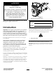
WARNING CALIFORNIA Proposition 65 Warning This product contains a chemical or chemicals known to the State of California to cause cancer, birth defects, or reproductive harm. The engine exhaust from this product contains chemicals known to the State of California to cause cancer, birth defects, or other reproductive harm. Figure 1 1. Model and serial number location Replacement Engine Owner’s Manuals may be ordered through the engine manufacturer. Model No. Serial No.
Contents Introduction .................................................................. 2 Safety ........................................................................... 4 Training ................................................................. 4 Preparation............................................................. 4 Operation............................................................... 4 Clearing a Clogged Broom........................................ 5 Maintenance and Storage...................
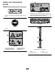
Safety – Replace gasoline caps securely and wipe up spilled fuel. Let engine and machine adjust to outdoor temperatures before starting to clear snow. Read and understand the contents of this manual before the engine is ever started. • This is the safety alert symbol. It is used to alert you to potential personal injury hazards. Obey all safety messages that follow this symbol to avoid possible injury or death. Operation • Never allow children to operate the machine.
• Never operate the machine without proper guards, plates, or other safety protective devices in place. • Use only attachments and accessories approved by the manufacturer of machine (such as wheel weights, counterweights, cabs, etc.). Clearing a Clogged Broom WARNING The rotating broom could cause serious injury. Always use caution when cleaning the broom. To clear the broom: • Park the machine on level ground. Stop engine, wait for all moving parts to stop, and remove the spark plug wire(s).
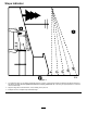
Slope Indicator G011841 Figure 3 1. The maximum slope you can safely operate the machine on is 10°. Use the slope indicator to determine the degree of slope of hills before operating. Do not operate this machine on a slope greater than 10°. Fold along the appropriate line to match the recommended slope. 2. Align this edge with a vertical surface, a tree, building, fence pole, etc. 3. Example of how to compare slope with folded edge.
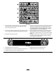
Safety and Instructional Decals Important: Safety and instruction decals are located near areas of potential danger. Replace damaged decals. 116-8505 112-9028 1. Explosion/Fire hazard–Read the Operator’s Manual. Stop engine before filling fuel tank. Leave 5/8 inch (16mm) at top of tank for fuel expansion-Do Not overfill tank. 1. Warning—stay away from moving parts; keep all guards in place. 117–2718 115-2903 1. Grease 116-8140 1. Thrown object hazard-Do Not operate when people and pets are in the area.
116-7370 1. Warning-Read the Operator’s Manual. Do Not operate this machine unless you are trained. Stay away from moving parts; keep all guards in place. 4. Warning-Stop engine and remove spark plug before adjusting, servicing, or cleaning machine and attachments. Before leaving the operator’s position, disengage broom, traction drive, and stop engine. Look behind and to the side before changing directions. Do Not carry passengers. 2. Thrown object hazard-Do Not operate when people and pets 5.
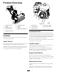
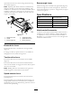
Product Overview G021739 Figure 5 Figure 4 1. Wheel-clutch lever 2. Handle 6. Traction-drive lever 7. Fuel cap 1. Choke control 4. Engine-recoil handle 2. Fuel-shutoff valve 5. Engine On/Off switch 3. Broom-angle lever 8. Broom 3. Throttle control 4. Broom-drive lever 9. Broom-height-adjustment pin 5. Speed-selector lever Fuel-Shutoff Valve The fuel-shutoff valve is the lower lever located on the rear, left side of the engine below the choke.
Broom-angle Lever squeezed. This allows for easier turning and maneuvering the machine (Figure 6). The broom-angle lever is located at the right handle (Figure 6). Note: Squeezing both wheel clutch levers simultaneously disengages the drive to both wheels (free-wheeling). This enables you to manually move the machine backward without stopping to shift it into a reverse gear. It also allows you to maneuver and transport the machine more easily when the engine is not running.
Operation DANGER When fueling, under certain circumstances, a static charge can develop, igniting the gasoline. A fire or explosion from gasoline can burn you and others and damage property. Fueling the Machine • Fuel tank capacity: 4.1 L (1.0 US gal) • Recommended Fuel: • Always place gasoline containers on the ground and away from your vehicle before filling.
Operating the Engine Positioning the Air-cleaner Cover for Cold or Warm Air Temperature Important: Running engine with air-cleaner cover positioned for cold weather operation in normal conditions can damage engine. The air-cleaner cover has 2 position: the cold- or normal-ambient air positions: Adjust the air-cleaner cover as follows: • When operating in a cold ambient air condition (cold Figure 9 air temperature and humidity)—position the air-cleaner cover with snowflake decal facing out (Figure 8). 1.
Note: If the ground speed is too fast, debris or snow will pile up in front of the broom causing the broom to bulldoze instead of sweep. This can damage the bristles and the drive line. 4. Slowly pull the engine-recoil handle until you feel resistance and then stop. Allow the recoil handle to return and then sharply pull it straight out (Figure 10). Note: Allow the rope to return slowly. 2. Slowly squeeze the left hand traction drive lever to the handle (Figure 12). 5.
WARNING Contact with a rotating broom can result in serious personal injury or death to the operator or bystanders. • To remove an obstruction from the broom; refer to Clearing a Clogged Broom (page 16). Figure 14 • Do not operate the machine if the broom drive lever is not functioning properly. Contact your authorized Toro dealer. 5. To stop the traction drive, release the traction drive lever.
• If the engine slows down under a load or the 3. Wait for all moving parts to stop before leaving the operating position. wheels slip, shift the machine into a lower gear. • If the front of the machine rides up, shift the 4. Turn the engine On/Off switch to the Off position. machine into a lower gear. If the front continues to ride up, lift up on the handles. 5. To adjust the broom height, remove and retain the pin from the adjuster sleeve and wheel tube of the caster (Figure 17). 4.
Transporting the Machine 3. Push the lever down with the thumb of your right hand (Figure 6). WARNING 4. Squeeze the left wheel-clutch lever to the handle and push the broom housing to the desired angle. 5. Once the broom is positioned, release the broom angle lever. Using ramps that are not strong enough or properly supported to load the machine onto the transport vehicle could be dangerous. The ramps could collapse, causing the machine to fall, which could cause injury. 6.
Maintenance Note: Determine the left and right sides of the machine from the normal operating position. Recommended Maintenance Schedule(s) Maintenance Service Interval Maintenance Procedure After the first 2 hours • Check the traction cable. • Check the broom cable. After the first 5 hours • Change the engine oil. Before each use or daily • Check the engine oil level. • Check the broom-shaft shear pin. • Check for loose hardware.
Pre Maintenance Procedures 2. Remove the belt cover and the engine shield. 1. Move the machine to a level surface. 3. Move the speed-selector lever to the R2 position. 2. Shut off the engine and allow it to cool. 4. Dip a long, clean, small-tipped paint brush in automotive engine oil and lightly lubricate the hex shaft (Figure 20). 3. Disconnect the spark-plug wire from the spark plug (Figure 18).
Figure 22 1. Alignment-arrow decal (normal ambient air position shown) 9. Secure the air-filter cover to the base with the latches. Figure 21 1. Air-filter base 2. Paper air filter Checking the Engine-oil Level 4. Cover 5. Latch on the air-cleaner cover (2) Service Interval: Before each use or daily Engine Oil Type: Toro 4–Cycle Premium Engine Oil 3. Foam pre-cleaner Use high-quality detergent oils (including synthetic) of API (American Petroleum Institute) service class SJ or higher.
Changing the Engine Oil Service Interval: After the first 5 hours Every 100 hours (more frequently in severe conditions). Oil capacity: 0.60 L (0.63 qt) Note: Drain the engine oil while the engine is warm. 1. Place a pan under drain fitting and remove the oil-drain cap (Figure 25). Figure 24 1. Filler neck 2. Dipstick 3. Remove the dipstick and wipe off the oil with a clean rag. Figure 25 1. Drain fitting 4.
4. Examine the plug for wear and damage (Figure 26). Important: Replace a cracked, fouled, or dirty spark plug. Do not clean the electrodes, because grit entering the cylinder can damage the engine. 1 2 3 4 G019300 Figure 26 1. Ground electrode 2. Center electrode 3. Insulator 4. Spark-plug gap 0.76 mm (0.030 inch) Figure 27 5. Check the spark-plug gap with a wire gauge. If necessary, adjust the gap to 0.76 mm (0.030 inch) by carefully bending the ground electrode (Figure 26). 1.
Drive System Maintenance 1. Loosen the jam nut (Figure 30). Checking the Tire Pressure 2. Loosen or tighten the turnbuckle to adjust the pin until it is the proper gap from the front edge of the slot (Figure 30). Service Interval: Every 50 hours 3. Tighten the jam nut (Figure 30). 1. Turn off the engine, wait for all moving parts to stop, and leave engine switch in the Off position. 2. Check the tire pressure in the drive tires. 3 3. Inflate the drive tires to 117 to 138 kPa (17 to 20 psi).
4. Support the spline shaft on either side of the gearbox. 5. Stand the broom core assembly on end so that the removable end retainer plate faces upward (Figure 34). Figure 32 1. Nut 2. Shear pin 4. If the shear pin is damaged, remove the pin, replace it, and secure the it with a nut. Figure 34 Replacing Worn or Damaged Broom Segments 1. Hardware 4. Support shaft 2. End-retainer plate 5. Alignment fingers Service Interval: As required. 3. Broom segment 1.
Maintaining the Belts Checking the Condition of the Belts Service Interval: Every 50 hours 1. Remove the knob and washer that secures the engine cover and the belt cover to machine (Figure 37). Figure 35 1. Broom-clutch assembly 3. 3.2 mm (1/8 inch) 2. Tab Adjusting the Broom Drive If the broom cable is not properly adjusted; refer to Checking the Broom Cable (page 23), and then perform the following steps: Figure 37 1. Knob 2. Washer 3. Engine cover 1. Loosen the jam nut (Figure 36). 4. Plate nut 5.
Note: Ensure that the belt is not twisted. 4. Align the spacer between the engine and the pulley shined and align the holes in the spacer, engine, and shield (Figure 38). 5. Secure the pulley guide to the machine with the bolts and washers (Figure 38) that you removed in step 2 of Removing the Broom-drive Belt (page 24). Removing the Traction Belt 1. Remove the broom-drive belt; refer to Removing the Broom-drive Belt (page 24) 2. Remove the hair pin from the traction-control rod (Figure 40). Figure 38 1.
Maintaining the Chassis 6. Slip the traction belt out of the groove of the traction pulley and up between the pulley and the friction wheel (Figure 42). Checking for Loose Hardware Service Interval: Before each use or daily 1. Visually inspect the machine for any loose missing hardware or any other possible problem. 2. Tighten all loose hardware before operating the machine. 3. Replace all missing hardware before operating the machine. Figure 42 1. Traction pulley 3. Friction wheel 2. Belt 7.
Storage Removing the Machine from Storage WARNING 1. Remove the spark plug and spin the engine rapidly using the starter to blow the excess oil from the cylinder. Gasoline fumes are highly flammable, explosive, and dangerous if inhaled. If you sore the machine in an area with an open flame, the gasoline fumes may ignite and cause an explosion.
Troubleshooting Problem The engine will not start, starts hard, or fails to keep running. Possible Cause 1. The fuel tank is empty. 1. Fill the fuel tank. 2. The fuel-shutoff valve is closed. 3. The throttle and choke are not in the correct position. 2. Open the fuel-shutoff valve. 3. Be sure the throttle control is midway between the Slow and Fast positions, and the choke is in the On position for a cold engine or the Off position for a warm engine. 4. Clean the fuel-valve screen and cup. 5.
Problem Possible Cause Corrective Action The broom wears out prematurely. 1. You are using the incorrect broom height. 1. Adjust the broom height. The speed selector is difficult to move or frozen in place. 1. The hex shaft needs lubrication. 1. Lubricate the hex shaft.
Notes: 30
Notes: 31
SWS Turf Renovation and Tree Care The Toro Warranty A limited warranty (see warranty periods below) Conditions and Products Covered The Toro Company and its affiliate, Toro Warranty Company, pursuant to an agreement between them, jointly warrant your Toro Products listed below to be free from defects in materials or workmanship. This warranty covers the cost of parts and labor, but you must pay transportation costs.