Form No. 3378-184 Rev A Walk-Behind Rotary Broom Model No. 23740—Serial No. 313000001 and Up Model No. 38700—Serial No. 313000001 and Up G021738 Register at www.Toro.com.
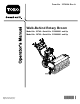
Replacement Engine Owner’s Manuals may be ordered through the engine manufacturer. Introduction WARNING CALIFORNIA Proposition 65 Warning Figure 1 This product contains a chemical or chemicals known to the State of California to cause cancer, birth defects, or reproductive harm. The engine exhaust from this product contains chemicals known to the State of California to cause cancer, birth defects, or other reproductive harm. 1. Model and serial number location Model No. Serial No.
Contents Introduction .................................................................. 2 Safety ........................................................................... 4 Training ................................................................. 4 Preparation............................................................. 4 Operation............................................................... 4 Clearing a Clogged Broom........................................ 5 Maintenance and Storage...................
Safety • Let engine and machine adjust to outdoor temperatures Read and understand the contents of this manual before the engine is ever started. • This is the safety alert symbol. It is used to alert you to potential personal injury hazards. Obey all safety messages that follow this symbol to avoid possible injury or death. before starting to clear snow. The operation of any powered machine can result in foreign objects being thrown into the eyes.
• Never operate the machine without good visibility or light. • Take all possible precautions when leaving the machine unattended. Shift into neutral, set the parking brake, stop the engine and remove the key. Clearing a Clogged Broom WARNING The rotating broom could cause serious injury. Always use caution when cleaning the broom. To clear the broom: • Park the machine on level ground. Stop engine, wait for all moving parts to stop, and remove the spark plug wire(s).
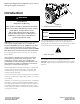
Slope Indicator G011841 Figure 3 1. The maximum slope you can safely operate the machine on is 10°. Use the slope indicator to determine the degree of slope of hills before operating. Do not operate this machine on a slope greater than 10°. Fold along the appropriate line to match the recommended slope. 2. Align this edge with a vertical surface, a tree, building, fence pole, etc. 3. Example of how to compare slope with folded edge.
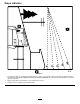
Safety and Instructional Decals Important: Safety and instruction decals are located near areas of potential danger. Replace damaged decals. 116-8505 112-9028 1. Explosion/Fire hazard–Read the Operator’s Manual. Stop engine before filling fuel tank. Leave 5/8 inch (16mm) at top of tank for fuel expansion-Do Not overfill tank. 1. Warning—stay away from moving parts; keep all guards in place. 117–2718 115-2903 1. Grease 116-8140 1. Thrown object hazard-Do Not operate when people and pets are in the area.
116-7370 1. Warning-Read the Operator’s Manual. Do Not operate this machine unless you are trained. Stay away from moving parts; keep all guards in place. 4. Warning-Stop engine and remove spark plug before adjusting, servicing, or cleaning machine and attachments. Before leaving the operator’s position, disengage broom, traction drive, and stop engine. Look behind and to the side before changing directions. Do Not carry passengers. 2. Thrown object hazard-Do Not operate when people and pets 5.
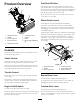
Fuel Shut-Off Valve Product Overview The fuel shut-off valve is the lower lever located on the rear left hand side of the engine below the choke. The fuel shut-off valve shuts off the flow of fuel when the machine will not be used for a few days, when parking inside a building, and during transport to and from the job. Move the lever to the left to shut off fuel. Move the lever to the right to turn on fuel. Wheel Clutch Levers Located below the right hand and left hand handles.
Note: Holding down the traction drive lever against the handle engages the traction drive to both wheels. Operation Speed Selector Lever Operating Instructions Located on the main console panel (Figure 5). Open the Fuel Shut-Off Valve The speed selector has 6 forward and 2 reverse settings. To change speeds, release the traction drive lever and shift the speed selector lever to the desired setting. The lever locks in a notch at each speed setting.
Adjusting the Traction Cable (page 18)) or contact your authorized Toro dealer. Driving Forward 1. Place the speed selector lever to the desired forward position, making sure it locks in the notch (Figure 6). Figure 8 Note: Similarly, squeezing the left wheel clutch lever turns the machine to the left. When you complete the turn, release the wheel clutch lever. The drive engages both wheels (Figure 9).
Operating the Broom 1. Set the engine throttle to the Fast position. 2. Place the speed selector lever into the desired position and slowly squeeze the left hand traction drive lever. DANGER When the machine is in operation, contact with rotating or moving parts will severely injure hands and feet. Important: Make sure the traction drive is engaged before operating the broom; otherwise the broom may drive the unit in the reverse direction.
Figure 11 1. 51-102 mm (2–4 inches) maximum width 2. Length of broom Figure 12 3. Swept area 1. Caster wheel tube 2. Positions to achieve 3 mm (1/8 inch) increments 7. Adjust the broom height if necessary. 3. Pin 4. Adjuster sleeve • To raise the broom in 3 mm (1/8 inch) increments, slightly raise the adjuster sleeve and insert the pin into the next pin hole below the current hole used.
the front of the machine on the pavement. Repeat if necessary. • If you cannot unclog the broom by bumping the front of the machine: – Park the machine on level ground. Stop the engine, wait for all moving parts to stop, and remove the spark plug wire(s). – Sharp objects can become entangled in bristles. Use gloves and caution when cleaning out the broom of foreign objects; not bare hands. Preventing Freeze-up • In snowy and cold conditions, some controls and moving parts may freeze.
Maintenance Note: Determine the left and right sides of the machine from the normal operating position. Recommended Maintenance Schedule(s) Maintenance Service Interval Maintenance Procedure After the first 2 hours • Check the traction cable. • Check the broom cable. After the first 5 hours • Change the engine oil. Before each use or daily • Check the engine oil level. • Check for loose hardware. • Check the broom shaft shear pin. Every 50 hours • Check the tire pressure.
Checking the Engine Oil Level 2. Visually inspect the machine for any loose hardware or any other possible problem. Tighten the hardware or correct the problem before operating. Service Interval: Before each use or daily Engine Oil Type: Toro 4–Cycle Premium Engine Oil Changing the Engine Oil 1. Turn off the engine and wait for all moving parts to stop. Make sure the unit is on a level surface. Service Interval: After the first 5 hours 2. Check the oil level once the engine is cold.
Checking the Spark Plug 2. Lubricate the broom angle lock pin fitting with NGLI grade #2 multi-purpose gun grease. Service Interval: Every 160 hours Remove the spark plug, check the condition and reset the gap, or replace with a new plug. See your Engine Owner's Manual. Checking the Broom Cable Service Interval: After the first 2 hours Yearly 1. Turn off the engine, wait for all moving parts to stop, and remove the spark plug wire(s). 2. Remove the belt cover and engine shield. 3.
8. Remove and retain the hardware from the end retainer plate. 9. Remove the damaged broom segment(s). Install the new segment(s) by staggering the metal ring alignment fingers as shown in Figure 18. Important: Damage may occur to the broom assembly if the broom segments are not properly installed. 10. Install the broom assembly onto the unit. Important: Make sure the bearing setscrews are tightened before operating the broom. Figure 17 1. Nut 2. Shear pin Adjusting the Traction Cable 4.
Storage WARNING • Gasoline vapors can explode. • Do not store gasoline more than 30 days. • Do not store the machine in an enclosure near an open flame. • Allow the engine to cool before storing it. Preparing the Machine for Storage Figure 20 1. Jam nut 1. On the last refueling of the year, add fuel stabilizer to fresh fuel as directed by the engine manufacturer. 2. Run the engine for 10 minutes to distribute the conditioned fuel through the fuel system. 3.
Removing the Machine from Storage 1. Remove the spark plug and spin the engine rapidly using the starter to blow the excess oil from the cylinder. 2. Install the spark plug by hand and then torque it to 20.4 N-m (15 ft-lb). 3. Connect the spark plug wire. 4. Perform the annual maintenance procedures as given in the Recommended Maintenance Schedule.
Troubleshooting Important: It is essential that all operator safety mechanisms be connected and in proper operating condition prior to use. When a problem occurs, do not overlook the simple causes. For example: starting problems could be caused by an empty fuel tank. The following table lists some of the common causes of trouble. Do not attempt to service or replace major items or any items that call for special timing of adjustments procedures (such as valves, governor, etc.).
Problem There is abnormal vibration. Possible Cause Corrective Action 1. The broom assembly is loose or damaged. 1. Tighten the hardware. Replace the broom assembly or contact an authorized service dealer. 2. 3. 4. 5. 2. 3. 4. 5. The engine mounting bolts are loose. engine pulley or idler pulley is loose. The engine pulley is damaged. The belt is damaged. Tighten the engine mounting bolts. Tighten the appropriate pulley. Contact an authorized service dealer. Install a new belt.
Notes: 23
SWS Turf Renovation and Tree Care The Toro Warranty A limited warranty (see warranty periods below) Conditions and Products Covered The Toro Company and its affiliate, Toro Warranty Company, pursuant to an agreement between them, jointly warrant your Toro Products listed below to be free from defects in materials or workmanship. This warranty covers the cost of parts and labor, but you must pay transportation costs.