Form No. 3402-253 Rev A 2024 Directional Drill Model No. Model No. Model No. Model No. Register at www.Toro.com. Original Instructions (EN) 23800A—Serial No. 315000001 and Up 23800C—Serial No. 315000001 and Up 23800TE—Serial No. 315000001 and Up 23800W—Serial No.
Read this information carefully to learn how to operate and maintain your product properly and to avoid injury and product damage. You are responsible for operating the product properly and safely. This product complies with all relevant European directives; for details, please see the separate product specific Declaration of Conformity (DOC) sheet. WARNING You may contact Toro directly at www.Toro.
Contents Electrical System Maintenance ....................................72 Servicing the Battery...............................................72 Charging the Battery ...............................................73 Jump-Starting the Machine ......................................73 Drive System Maintenance .........................................74 Checking the Oil Level for the Planetary Drive ................................................................74 Changing the Oil for the Planetary Drive.
Preparation Safety • Evaluate the terrain to determine what accessories and Improper use or maintenance by the operator or owner can result in injury. To reduce the potential for injury, comply with these safety instructions, and pay attention to the safety alert symbol , which means Caution, Warning, or Danger—“personal safety instruction.” Failure to comply with the instructions may result in personal injury or death. attachments are needed to properly and safely perform the job.
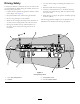
Driving Safety • Use care when loading or unloading the machine onto a You drive the machine to and from the work site with the use of a tethered remote. When driving the machine, observe the following safety precautions: • Watch for traffic when crossing roadways. trailer. • Check for overhead clearances (i.e. branches, doorways, electrical wires) before driving under any objects and do not contact them. • Operate the drive pendant alongside the machine outside of the danger zone (Figure 3).
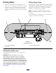
Drilling Safety Drilling Danger Zone • Always lower the safety bar before drilling (Figure 4). The danger zone is the area within and around the machine where a person is exposed to the risk of injury. This proximity includes where a person can be reached by operational movement of the machine, its working devices, auxiliary equipment, or swinging/falling equipment. • Ensure that no one approaches a pipe while it is spinning. The pipe can snag on clothing and cause amputation or death.
Gas Line Safety Utility Line Color Refer to the following table for the proper utility line and the corresponding utility line color (USA and Canada). Utility Line WARNING If you damage a gas line, an immediate explosion and fire hazard could occur. Leaking gas is both flammable and explosive and may cause serious injury or death.
Maintenance and Storage – Do not refuel the machine indoors. • Do not touch parts which may be hot from operation. – Do not store the machine or fuel container inside where there is an open flame, such as near a water heater or furnace. Allow them to cool before attempting to maintain, adjust, or service. – Do not fill a container while it is inside a vehicle, trunk, pick-up bed, or any surface other than the ground. • Lower the thrust frame, stop the engine, and remove the key.
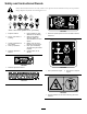
Safety and Instructional Decals Safety decals and instructions are easily visible to the operator and are located near any area of potential danger. Replace any decal that is damaged or lost. Battery Symbols Some or all of these symbols are on your battery 1. Explosion hazard 6. Keep bystanders a safe distance from the battery. 2. No fire, open flame, or smoking. 7. Wear eye protection; explosive gases can cause blindness and other injuries 3. Caustic liquid/chemical burn hazard 4.
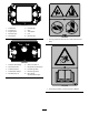
125-1641 1. Forward left 6. Forward right 2. Increase rpm 7. High 3. Engine speed 8. Track speed 4. Decrease rpm 9. Low 10. Reverse right 5. Reverse left 125-6107 1. Crushing hazard of hand and foot—keep hands and feet away. 125-1645 1. Pull back drill carriage 6. Wrench controls on 2. Reverse left track 7. Drill spindle clockwise spin 3. Forward left track 8. Forward right track 4. Forward drill carriage 9. Reverse right track 5. Drill fluid pump on 10.
125-6109 1. Electrical shock hazard—when the Zap-Alert system is activated by a power strike, do not leave the operator’s position or touch the ground and the machine at the same time; the machine will be energized with electrical power. 125-6114 1. Stored energy hazard—do not use tools; read the Operator’s Manual. 125-6111 1. Stake up 6. Stake up 2. Stake down 7. Stake spin counterclockwise 8. Stake down 3. Stake spin counterclockwise 4. Stake spin clockwise 5. Left stake 125-6115 1.
5-6116 1. Falling hazard—do not move the machine when someone is in the operator’s position. 125-6118 1. Crushing hazard, machine movement—read the Operator’s Manual. 125-6119 1. Entanglement hazard—keep away from moving objects. 125-6117 1. Falling hazard—do not stand on the machine while it is moving. 125-6120 1. Raise drill carriage 12 4. Lower left stabilizer 2. Lower drill carriage 5. Raise right stabilizer 3. Raise left stabilizer 6.
125-6123 1. Load pipes from back row first. 125-6121 1. Engine—heating light 5. Fluid pump on 2. Engine—stop 6. Fluid pump off 3. Engine—run 7. Drill-pendant receptacle 4. Engine—start 8. Drive-pendant receptacle 125-6124 1. Center the pipe joint between the upper and lower wrenches. 125-6122 1.
125-6125 1. Warning—read the Operator’s Manual. 2. Explosion hazard; electrical shock hazard—do not dig before calling local services. 3. Press to apply tread-joint compound. 4. Press and hold for maximum drilling fluid pressure; release to stop the flow. 5. Press to turn the drilling-fluid pump on or off. 125-6126 6. Press and hold to move the drill carriage at high speed up or down the drill frame. 7. Mode I—spin drill spindle clockwise.
125-6129 1. Hot surface—keep away from hot surfaces. 125-6140 1. Rotate the chair. 125-6152 1. Move seat forwards and backwards. 125-6131 1. Warning—stay at least 3 m (10 ft) away from the machine. 125-6694 1.
125–8483 125-8473 1. Hydraulic fluid; read the Operator’s Manual. 1. Explosion hazard—wear eye protection. 3. Fire hazard—keep open flames away. 2. Caustic liquid/chemical burn hazard—rinse affected area and seek medical assistance. 4. Poison hazard—do not tamper with the battery. 125-6113 1. Warning—read the Operator’s Manual. 4. Warning—keep away from moving parts; keep all guards and shields in place. 2. Warning—do not operate the machine unless you are trained. 5.
125-6112 1. Exit-side lockout—reset light 14. Work lights—Off 2. Exit-side lockout—drill-enabled light 15. Press and hold to increase engine speed. 3. Receiver-battery-status light 16. Engine speed 4. Engine—start 17. Press and hold to decrease engine speed. 5. Press down to stop the engine; pull up to start the engine. 18. Mode I—left trigger released, extends pipe gripper toward drill frame; left trigger pressed, opens lower wrench. Mode II—spin drill spindle clockwise. 6.
Product Overview Figure 5 1. Drill carriage 6. Front hood 2. Zap-alert strobe 7. Right stabilizer 3. Operator seat 8. Rear hood 4. Control panel 9. Thrust frame 5.
Figure 6 1. Stake-down cage 5. Rear-control panel 2. Pipe holder 6. Left stabilizer 3. Safety bar 7. Stake-down plate 4.
Figure 7 4. Upper wrench 1. Thrust frame 2. Drill carriage 5. Lower wrench 3. Drill spindle 6.
Controls Operator-Controls Covers Refer to the following sections for the appropriate machine controls: The covers protect the operator controls from adverse weather conditions, such as rain, wind, sunlight, etc. Remove them before using the machine and replace them before leaving the machine for the day. Each cover is secured with 2 screws as shown in Figure 9.
Exit-Side Lockout—Drill-enabled Light To release the platform and swing it out or in, press up on the front platform latch (Figure 11). This light (Figure 12) illuminates green when the exit-side-lockout feature has been turned off and reset and the machine is ready to drill. Exit-Side Lockout—Reset Switch Press this switch (Figure 12) to enable drilling operation when the reset light illuminates.
Left Joystick—Mode I Front Button Note: The joystick controls vary depending on the control mode you select when powering up the machine. There are 2 control modes: Mode I and Mode II; refer to the Control-Select Screen in the Software Guide for information on setting the control mode. • Left trigger pressed—press this button to resume the 1 previously set auto-drill speed. Press and hold this button to increase the auto-drill speed. • Left trigger released—press this button to close the pipe gripper.
Left Joystick—Mode II Front Button Note: The joystick controls vary depending on the control mode you select when powering up the machine. There are 2 control modes: Mode I and Mode II; refer to the Control-Select Screen in the Software Guide for information on setting the control mode. • Left trigger pressed—press this button to resume the 1 previously set auto-drill speed. Press and hold this button to increase the auto-drill speed.
Right Joystick—Mode I Lower Button Note: The joystick controls vary depending on the control mode you select when powering up the machine. There are 2 control modes: Mode I and Mode II; refer to the Control-Select Screen in the Software Guide for information on setting the control mode. Press this button to turn the drilling-fluid pump on or off. 1 Trigger Press and hold the trigger to move the drill carriage at high speed up or down the drill frame.
Right Joystick—Mode II Lower Button Note: The joystick controls vary depending on the control mode you select when powering up the machine. There are 2 control modes: Mode I and Mode II; refer to Control-Select Screen in the Software Guide for information on setting the control mode. Press this button to turn the drilling-fluid pump on or off. 1 Trigger Press and hold the trigger to move the drill carriage at high speed up or down the drill frame.
Exit-Side-Lockout System (Standard Range) Engine, Key Switch The key switch has 3 positions as follows (Figure 18): The exit-side-lockout system provides the individuals working around the machine with a means to disable the drill pipe from rotating and thrusting. 1 2 For more information and instructions, refer to the Operator’s Manual for the Exit-side-lockout system.
Drive Pendant Drill Frame and Stabilizer Controls Refer to Figure 17 for location. 1 2 3 1 3 2 4 5 g021843 Figure 19 1. Drill-frame tilt lever 3. Right-stabilizer lever 2. Left-stabilizer lever g021855 Figure 20 Stabilizer Levers Use the stabilizer levers to raise and lower the stabilizers. Note: The DRIVE/DRILL switch on the operator panel must be switched to the DRIVE position for this function to work. 1. Engine-speed switch 4. Drive-speed switch 2. Drive-direction joystick 5.
Drive-Speed Switch Left Switch The switch sets the speed at which the machine will travel. Move the switch up for high speed or down for low speed. • When connected to the drill-pendant receptacle, move Operator-Presence Switch • When connected to the drive-pendant receptacle, move this switch up to move the drill carriage forward or down to move the drill carriage rearward. this switch up to move the left track forward or down to move the left track rearward.
Battery-Disconnect Switch Specifications Open the front hood to access the BATTERY -DISCONNECT switch; refer to Opening the Front Hood (page 58). Note: Specifications and design are subject to change without notice. The BATTERY -DISCONNECT switch is located to the right of the engine; it is used to electrically disconnect the battery from the machine. Machine Turn the BATTERY -DISCONNECT switch to the ON or OFF position to perform the following: Width 131 cm (51.
Operation Refer to Preparing the Job Site and the Machine (page 39) for instructions on preparing the job site and the machine. Note: Determine the left and right sides of the machine from the normal operating position. 4. Drill the bore. You drill the bore in three stages: Understanding Horizontal Directional Drilling A. Entry In the entry phase of the bore, you push the drill bit and head into the ground at an angle of up to 16 degrees.
Gathering Site Information DANGER Contacting underground hazards with the machine while drilling or reaming can cause explosion, electrocution, breathing problems, severe trauma, and death to you or bystanders.
– Electrical power lines – Crystalline silica and other dust If you will be drilling through or cutting concrete, sand, or other substances that create dusts or fumes, you need to ensure that you and all workers wear breathing protection to protect your lungs from the dust. DANGER Drilling into an electric power line will cause the machine to become electrified and may electrocute you or any bystanders. ◊ Keep bystanders and spectators away from the job site, including the complete bore path.
Planning the Bore Path Before setting up the job site, you need to plan the bore path, including the following: 1 4 3 2 5 g021764 Figure 24 1. Bore entry 4. Obstacle 2. Beginning-of-bore-at-depth point 5. End-of-bore-at-depth point and bore exit 3. Bore depth • Bore entry needed for steering the drill to the surface, typically 9 to 15 m (30 to 50 ft) from the end-of-the-bore-at-depth point. The is the location where you setup the machine and the drill bit enters the ground.
1 g021765 Figure 25 1. 20 cm (8 inches) This flexibility is often rated in materials as a minimum bend radius, which is the radius of the circle formed if the material or pipes, connected together, were bent to form a giant circle. The minimum radius of a circle made with the pipe used with this machine is 31 m (101 ft). 1 2 • Entry pitch g021767 The entry pitch is the angle at which the machine enters the ground.
Note: The depths given in the following table are for 3 m (10 ft) of combined drill head and pipe. As you steer up, the pitch of the steered section will change and can be monitored with the receiver. Use the following table to identify how many lengths of pipe will be necessary to insert and steer to the beginning point and help you choose an entry point.
Given the above information, you can calculate the number of rods required to reach your beginning point at the appropriate depth. Toro recommends that you start the entry point a distance back from your beginning-at-depth point by the same distance as the length of pipes you will need to reach that point. This will ensure that you have enough extra space so you will not need to over-steer and damage the pipes.
• You insert the first 3 m (10 ft) of drill bit/pipe into the The following example illustrates the process given an installation using the machine at an 18% pitch on level ground: ground with no steering. The end of the drill bit will be 53 cm (21 inches) deep (Figure 29). 6 1 2 3 4 5 g021769 Figure 29 1. 18% pitch 3. 96 cm (38 inches) 5. 119 cm (47 inches) 2. 53 cm (21 inches) 4. 114 cm (45 inches) 6. 10.
Testing the Zap-Alert System Preparing the Job Site and the Machine The Zap-Alert system is an electric strike sensing device on the machine that triggers a strobe light and audible alarm in the event that the drill bit, reamer, or stake breaks into an energized power line. In the event of an electric strike, the machine will become energized, setting off the alarm.
If either the audible alarm or the strobe light failed to trigger when you pressed the TEST button, have them repaired before drilling with the machine. Mounting a Fire Extinguisher Mount your fire extinguisher below the operator seat (Figure 32). Note: A fire extinguisher is not provided with the machine. The recommended fire extinguisher is a dry chemical fire extinguisher approved for class B and C fires. Figure 30 1. Test button 2. Zap-alert tester 5. Reset button 6. Alligator clips 3.
Loading Drill Pipes into the Pipe Holder Before using the machine, fill the pipe holder with up to 40 drill pipes. Figure 33 1. Pipe 2. Male end 3. Clevis pins Adding Fuel 1. Remove the clevis pins from the pipe holder (Figure 33). Service Interval: Before each use or daily—Check the fuel level. 2. Insert the pipes from the top with the male threaded pipe ends toward the front of the machine (Figure 33).
Use of summer grade fuel above -7° C (20° F) will contribute toward longer fuel pump life and increased power compared to winter grade fuel. • If this is not possible, then refuel such equipment on Important: Do not use kerosene or gasoline instead of diesel fuel. Failure to observe this caution will damage the engine. • If a fuel dispenser nozzle must be used, keep the nozzle in a truck or trailer from a portable container, rather than from a fuel dispenser nozzle.
Driving the Machine Adjusting the Carriage Pressure 1. Walk around the machine to ensure that no one is near it. Ensure that all bystanders are clear of the area where you will be moving the machine. 2. Connect the drive pendant to the right receptacle on the bottom of the rear control panel. 3. With the pendant in hand, walk at least 6 feet to the side of the machine. Be sure to keep this safe distance whenever moving the machine. 4. Press and hold the OPERATOR-PRESENCE button on the drive pendant. 5.
11. After driving a few miles, pull over and check to ensure that all chains are still tight and that the machine has not moved. To unload the machine, reverse the above procedure. Figure 35 1. Upper pins 2. Lower pins 3. Place a block at the front and rear of the trailer and/or truck tires. 4. Using the drive pendant, set the engine speed to slow, and the drive speed to slow. 5. Using the drive pendant, carefully drive the machine forward or rearward up the ramp and into position on the trailer. 6.
Setting Up the Drill Head and Tracking System The drill head consists of two parts, the drill bit and the sonde housing (Figure 37). Figure 37 1. Sonde housing Figure 38 2. Drill bit 1. Sonde housing 4. Housing cover 2. Screws 5. Housing 3. Drill bit Drill bits vary in size and type to meet the various soil conditions you may need to drill through. Some of the possibilities are as follows: 3. Insert the sonde beacon with the forward end toward the drill bit into the sonde housing (Figure 39).
Figure 42 1. Rear platform latch Deploying the Zap-Alert System The Zap-Alert system is an electric strike sensing device on the machine that triggers a strobe light and audible alarm in the event that the drill bit, reamer, or stake breaks into an energized power line. In the event of an electric strike, the machine will become energized, setting off the alarm. The operator’s platform is electrically isolated from the rest of the machine to protect you. Figure 40 1. Screw 2. Cover 4.
3. If the ground is dry where you put the stake, soak it with water before using the machine to ensure good electrical contact. DANGER If the Zap-Alert system activates while drilling, the machine, except for the operator’s platform, will become energized. If you step off the operator platform or if someone touches the machine or wet ground near the machine or in the bore, you or they could be electrocuted causing serious injury or death. Lowering the Stakes 1.
Connecting to a Drilling-Fluid Source When drilling and reaming, you pump a mixture of bentonite clay, water, and sometimes other ingredients, collectively called drilling fluid or “Mud”, through the pipe and into the bore. This drilling fluid, or “Mud”, does the following for your bore: • Lubricates the drill head • Loosens the soil into which the drill is cutting • Penetrates and binds loose soil to keep them from collapsing on the bore pipe.
Setting Up the Pump to Use a Natural Water Source Drilling the Bore To set up a pump to use a natural water source, you must ensure that you use the Y-screen to filter all materials other than water. Starting the First Pipe 1. Ensure that all bystanders are away from the machine and that the exit-side lockout is On. To install the Y-screen perform the following tasks: 1. Remove the pump-inlet cap (Figure 48). 2.
Installing the Drill Head 1. Using the exit-side-lockout transmitter, enable the exit side lockout. WARNING If the drill rotates or extends while you or others are manually working on the drill bit or pipe in front of the machine, the worker could get caught in the bit or pipe causing serious injury, amputation, or death. • Enable the exit-side lockout on the exit-side-lockout transmitter before approaching the dill bit or pipe when attached to the machine. This will disable the drill carriage.
5. Using the upper wrench, clamp the lead bar and tighten it to full machine torque. 4. Rotate the drill head counterclockwise until the spindle is completely removed from the pipe. 6. Using the exit-side-lockout transmitter, enable the exit-side lockout. 5. Spray the spindle with thread joint compound, then return the drill carriage to the upper end of the frame. 7. Double check the drill head and bit to ensure that the fluid ports are clean and free from obstructions. 6.
the way back and change to a drill bit appropriate for drilling through the new soil type. When drilling, the receiver operator follows the drill head as it progresses. The receiver receives signals from the sonde in the drill head identifying its position, depth, pitch, direction, transmitter temperature, and orientation in the soil. The remote console is a screen that remains near you (the drill operator) to show you the information from the receiver while drilling so you can make steering decisions.
Connecting the Reamer and Product WARNING 1 If the drill rotates or extends while you or others are manually working on the drill bit or pipe in front of the machine, the worker could get caught in the bit or pipe causing serious injury, amputation, or death. • Enable the exit-side lockout on the exit-side-lockout transmitter before approaching the dill bit or pipe when attached to the machine. This will disable the drill carriage.
Finishing the Job 17. Rotate the drill spindle counterclockwise moving rearward slowly until the spindle fully separates from the pipe. Complete the following after each day of use: 18. Retract the pipe gripper arms. • Connect the hand spray gun to the pump and clean the machine with clean water; refer to Cleaning with the Spray-Hose Attachment (page 88). 19. Rotate the pipe cam to the desired row. Note: Fill the outside rows first.
Adjusting the TJC-spray Volume Filling the TJC Applicator 1. Stop the machine and stop the engine. To adjust the volume of thread-joint compound that is delivered by the applicator, complete the following: 2. Open the stake-down-guard door. 1. Loosen the jam nut on the adjustment bolt located on top of the TJC-applicator piston (Figure 55). 1 2 3. Loosen the wing nuts securing the cover straps to the machine (Figure 56). 3 1 2 3 4 5 g021846 g021845 Figure 56 Figure 55 1. Adjustment bolt 3.
Moving a Disabled Machine Whenever the machine is stopped and the engine is not running, the hydrostatic brakes automatically engage. Do not attempt to tow the machine if it cannot move under its own power. If possible, repair the machine at the site. If this is not possible, use a crane and a spreader bar to lift the machine onto a trailer, using the lift points shown in Figure 57. Figure 57 Repeat lift points on other side 1. Spreader bar 2.
Maintenance Note: Determine the left and right sides of the machine from the normal operating position. Recommended Maintenance Schedule(s) Maintenance Service Interval Maintenance Procedure After the first 100 hours • Check the gearbox drive oil. • Change the gearbox-drive oil. After the first 250 hours • Adjust the valve clearance. • Change the planetary oil. Before each use or daily • • • • • • • • • • Check the fuel level. Grease the machine. (Grease immediately after every washing).
CAUTION If you leave the key in the ignition switch, someone could accidently start the engine and seriously injure you or other bystanders. Remove the key from the ignition before you do any maintenance. WARNING Improperly servicing or repairing the machine may cause injury or death. If you do not understand the service procedures for this machine, contact your dealer or see the service manual for this machine. WARNING Raised equipment on the machine without an operator may cause injury or death.
Using the Cylinder Lock 2. Pull the hood latch out (Figure 60). WARNING The thrust frame may lower when it is in the raised position, causing serious injury or death. Install the cylinder lock before performing maintenance that requires the thrust frame to be raised. Installing the Cylinder Lock 1. Start the engine. 2. Lower the thrust frame to the fully-lowered position. 3. Stop the engine. 4. Position the cylinder lock over the cylinder rod (Figure 62). 5.
Lubrication 7. Store the cylinder lock next to the anti-freeze tank (Figure 63). Greasing the Machine Service Interval: Before each use or daily (Grease immediately after every washing). Grease type: General-purpose grease. 1. Park the machine on a level surface, stop the engine, and remove the ignition key. 2. Clean the grease fittings with a rag. 3. Connect a grease gun to each fitting. 4. Pump grease into the fittings until grease begins to ooze out of the bearings (approximately 3 pumps).
Figure 68 Thrust-frame pivot pin (Under side of machine) Figure 65 Front-pipe elevator and cam cylinder (drill/carriage side) Figure 69 Rear-pipe elevator (operator’s side) Figure 66 Rear-pipe elevator and cam cylinder (drill/carriage side) Figure 70 Front-pipe elevator (operator’s side) Figure 67 Stabilizer cylinder and foot (drill/carriage side; repeat on other side) 61
Figure 71 Stakedown motors Figure 72 Carriage-roller bearings (operator’s side shown; repeat on other side) Figure 73 Gearbox float (operator’s side shown; repeat on other side) Figure 74 Track roller (operator’s side shown; repeat on other side) 62
Engine Maintenance Cleaning the Crankcase-Vent Tube Service Interval: Before each use or daily—Check the crankcase-vent tube and clean it if necessary. 1. Park the machine on a level surface, stop the engine, and remove the ignition key. 2. Open the front hood; refer to Opening the Front Hood (page 58). Figure 75 Rear-cam bearing (operator’s side) 3. Gently pull the crankcase-vent tube out (Figure 77). 4. Clean the end of the crankcase-vent tube (Figure 77).
• Servicing the Air-Cleaner Cover it is necessary only increases the chance of dirt entering the engine when the filter is removed. Be sure the cover is seated correctly and seals with the air-cleaner body. Service Interval: Every 50 hours—Remove air cleaner cover and clean out debris. Do not remove the filter. Checking the Air-Cleaner Indicator Removing the Air-Cleaner Cover Service Interval: Before each use or daily 1. Start the engine. 2.
Servicing the Air-Cleaner Filter Service Interval: Every 250 hours Replace the filters only when the “Check Air Filter” indicator appears on the display screen; refer to Checking the Air-Cleaner Indicator (page 64). Note: Contact your Authorized Toro Dealer to order replacement filters. 1. Park the machine on a level surface, stop the engine, and remove the ignition key. 2. Open the front hood. 3.
of low viscosity oil can decrease engine life because of wear (Figure 83). Toro Premium Engine Oil is available from an Authorized Toro Service Dealer in either 15W-40 or 10W-30 viscosity with API classification CH-4 or higher. See the parts catalog for part numbers. Checking the Engine-Oil Level Service Interval: Before each use or daily—Check the engine-oil level. Figure 82 1. Park the machine on a level surface, stop the engine, and remove the ignition key. 1. Safety filter 2. Open the front hood. 3.
8. Align the oil filter to the oil-filter adapter and rotate it clockwise until the seal of the oil filter contacts the oil-filter adapter (Figure 86). Note: Do not use an oil filter strap wrench to install the new oil filter. The wrench can dent an oil filter and therefore cause a leak. 9. Hand tighten the oil filter an additional 1/2 turn (Figure 86). G021582 10. Remove the oil pan or rags you placed in step 3 and dispose of the used oil according to local codes.
Servicing the Spark Arrestor (If Equipped) Service Interval: Every 250 hours—Clear the spark arrestor in the muffler of carbon buildup. 1. Park the machine on a level surface, stop the engine, and remove the ignition key. 2. Remove the pipe plug from the clean-out port at the lower side of the muffler. WARNING Figure 88 1. Filler neck 2. Oil-fill cap The muffler may be hot and could cause injury. 3. Funnel Be careful not to touch the hot muffler.
Fuel System Maintenance and drain any water and sediment from the fuel filter (Figure 89). Note: If the fuel-water separator has any water or sediment, also drain the water and sediment from the fuel tank; refer to Draining Water from the Fuel Tank (page 69). DANGER Under certain conditions, diesel fuel and fuel vapors are highly flammable and explosive. A fire or explosion from fuel can burn you and others and can cause property damage. 5.
Priming the Fuel System Replacing the Fuel Filters Note: Prime the fuel system whenever any of the following occur: • You drained water from the fuel filter. • You replaced the fuel filter. • You ran the engine until the fuel tank is empty or drained the fuel tank. 1. Park the machine on a level surface, stop the engine, and remove the ignition key. 2. Open the front hood. 3. Ensure that the engine and the exhaust system are cool. 4. Ensure that the fuel tank is at least 1/4 full. 5.
4. Start the engine and check for leaks at the fuel filters. Checking Fuel Lines and Connections Service Interval: Every 500 hours/Yearly (whichever comes first)—Inspect the fuel lines and connections. Inspect the fuel lines and connections for deterioration, damage, or loose connections. Draining and Cleaning the Fuel Tank Service Interval: Every 1,000 hours/Yearly (whichever comes first)—Drain and clean the fuel tank. Figure 92 1. Filter adapter 6. Hose clamp 2. Secondary-filter element 7. Arrow 3.
Electrical System Maintenance WARNING A battery contains sulfuric acid, which can cause serious burns; and they can produce explosive gases. Servicing the Battery • Avoid contact with skin, eyes, or clothing; flush affected areas with water. Service Interval: Every 50 hours—Check the battery condition • If taken internally, drink large quantities of water or milk. Do not induce vomiting. Seek medical attention immediately.
Charging the Battery Battery-Charger Table WARNING Charging the battery produces gasses that can explode. Charger setting Charging time 4 to 6 amperes 30 minutes 25 to 30 amperes 10 to 15 minutes 8. When the battery is fully charged, unplug the charger from the electrical source, then disconnect the charger leads from the battery posts (Figure 93). Do not smoke near the battery and keep sparks and flames away from battery. Important: Keep the battery fully charged.
Drive System Maintenance Checking the Oil Level for the Planetary Drive Service Interval: Every 50 hours—Check the planetary-drive oil level (Also, check if external leakage is observed). Oil specification: SAE 85W-140 API classification level GL4 Figure 94 1. Jumper-cable clamp (positive) 4. Ground point (unpainted bolt) 2. Jump post 5. Jumper-cable clamp (negative) Planetary drive oil capacity: approximately 1.4 L (1.5 US qt) Toro Premium Gear Oil is available from an Authorized Toro Service Dealer.
Changing the Oil for the Planetary Drive Service Interval: After the first 250 hours—Change the planetary oil. Every 800 hours—Change the planetary oil (or yearly, whichever comes first). Note: Change the oil when it is warm, if possible. 1. Park the machine on a level surface. 2. Clean the area around the oil-level plug (Figure 95). 3. Rotate the planetary drive until the oil-drain plug is directly below the oil-level plug (Figure 95). 4. Stop the engine and remove the key. Figure 96 5.
9. Place the guard back into place and install the 2 bolts (Box A of Figure 97). 10. Install the 2 other bolts securing the lid onto the gearbox (Box A of Figure 97). 11. Torque the bolts to 23 to 29 N∙m (17 to 21 ft-lb). Servicing the Tracks Service Interval: Before each use or daily—Check the track tension. WARNING Grease in the hydraulic track is highly pressurized; ensure that the track-tension grease valve is not loosened more than one revolution at a time.
Cooling System Maintenance 5. Remove excess grease from around the valve. 6. Install the cover and retaining bolts. 7. Repeat steps 2 through 6 to tighten the track tension on the other side. Coolant specification: 50/50 solution of ethylene-glycol antifreeze and water or equivalent Loosening the Track Tension Engine and Radiator coolant capacity: 16.77 L (17.7 US qt) If the track seems tight, loosen the track tension as follows: 1.
Checking the Coolant Level in the Reservoir 1. Park the machine on a level surface, stop the engine, and remove the ignition key. 2. Allow the engine to cool. Service Interval: Before each use or daily 3. Open the front hood and rear hood. Important: Do not remove the radiator filler cap during this procedure. 1. Park the machine on a level surface, stop the engine, and remove the ignition key. 2. Allow the engine to cool. 3. Open the front hood. 4. Check the coolant level in the reservoir (Figure 100).
Checking the Condition of Cooling-System Components Service Interval: Every 300 hours/Yearly (whichever comes first) Check the condition of the cooling system for leaks, damage, dirt, and loose hoses and clamps. Clean, repair, tighten, and replace the components as necessary. Checking the Concentration of the Coolant Figure 102 Service Interval: Every 1,000 hours/Yearly (whichever comes first)—Check the concentration of the coolant before the winter season. 1. Radiator drain plug 6.
D. Operate the engine for 5 minutes or until the coolant temperature indicates 82°C (180°F), and then stop the engine. CAUTION The water is hot and can cause burns. Stay away from the discharge end of the coolant drain plug. Figure 103 1. Filler neck (radiator) E. Open the drain plug and drain the water into a drain pan. 3. Coolant system cleaning solution 2. Funnel C. Close the drain plug (Figure 102). Important: Do not install the radiator cap. D.
Belt Maintenance 3 Servicing the Engine-Drive Belt 2 1 WARNING Contacting a rotating belt can cause serious injury or death. Stop the engine and remove the ignition key before working near belts. G022028 Figure 105 1. Coolant level (at the bottom of the filler neck) Checking the Condition of the Belt 3. Coolant (50/50 ethylene glycol and water or equivalent) Service Interval: Every 250 hours 1. Park the machine on a level surface, stop the engine, and remove the ignition key. 2. Filler neck 2.
Adjusting the Tension of the Belt Checking the Tension of the Belt 1. Park the machine on a level surface, stop the engine, and remove the ignition key. Service Interval: Every 1,000 hours 1. Park the machine on a level surface, stop the engine, and remove the ignition key. 2. Open the front hood. 2. Open the front hood. 3. Loosen the nut and bolt at the pivot point for the alternator (Figure 107). 3. Align a straight edge over the drive belt and across the pulleys as shown in Figure 106.
Hydraulic System Maintenance WARNING Hydraulic fluid escaping under pressure can penetrate skin and cause injury. • If hydraulic fluid is injected into the skin it must be surgically removed within a few hours by a doctor familiar with this type of injury. Gangrene may result if this is not done. Servicing the Hydraulic Fluid The hydraulic reservoir is filled at the factory with approximately 102 L (27 US gallons) of high-quality hydraulic fluid.
Changing the Hydraulic-Fluid Return Filter 1 Service Interval: Every 500 hours/Every 6 months (whichever comes first) 2 1. Park the machine on a level surface, stop the engine, and remove the ignition key. 2. Open the front hood. 3. Clean the area around the filler neck and cap of the hydraulic tank. 4. Open the hydraulic-tank cap (Figure 109). 3 4 G022167 Figure 108 1. Hydraulic-tank breather 2. Hydraulic-tank cap 3. Full oil level (operating temperature) Figure 109 4. Low oil level 1.
4. Place a large draining container under the hydraulic fluid tank. 5. Remove the drain plug from the bottom of the tank. 6. Clean the threads on the drain plug and apply 3 layers of PTFE sealing tape. 7. Drain the hydraulic fluid flow into the container. Important: The capacity of the hydraulic-fluid tank is 102 L (27 US gallons), so ensure that you have a container of at least 114 L (30 US gallons) to drain the fluid into. 8. Install the drain plug when the hydraulic fluid stops draining. Figure 110 9.
Checking the Hydraulic Lines and Hoses Drilling-fluid Pump Maintenance Service Interval: Every 2 years—Replace moving hoses. Inspect the hydraulic lines and hoses daily for leaks, kinked lines, loose mounting supports, wear, loose fittings, weather deterioration, and chemical deterioration. Make all necessary repairs before operating.
Preparing the Drilling-Fluid System for Cold Weather 4. Ensure that the oil is at the oil-fill line as shown in Figure 111. Note: If the oil is below the oil-fill line, refer to step 8 of Changing the Drilling-Fluid Pump Oil (page 87) and add the necessary amount of oil. Prepare the machine as follows after drilling if the temperature will be below 0° C (32° F). Changing the Drilling-Fluid Pump Oil 1. Park the machine on a level surface, stop the engine, and remove the ignition key.
Cleaning 1 Cleaning with the Spray-Hose Attachment Service Interval: Before each use or daily The machine comes with a spray-hose attachment that you can use to clean the machine and pipes. Important: Do not spray any electronic component of the machine and ensure that the hood is down before cleaning the machine with the spray-hose attachment.
7. Turn the drilling-fluid pump to the ON position through the display screen; refer to the Main Drill Functions Displayed in the Pressure Screen in the Software Guide. 8. Using the spray-hose attachment, hold down the lever and spray down the machine and pipes. Cleaning Plastic and Resin Parts Figure 118 Avoid using gasoline, kerosene, paint thinner, etc. when cleaning plastic windows, the console, the instrument cluster, the monitor, gauges, etc.
Storage 1. Stop the engine and remove the key. 2. Remove dirt and grime from the entire machine. Important: You can wash the machine with mild detergent and water. Avoid excessive use of water, especially near the control panel, engine, hydraulic pumps, and motors. 3. Service the air cleaner; refer to Servicing the Air-Cleaning System (page 63). 4. Grease the machine; refer to Greasing the Machine (page 60). 5. Charge the battery; refer to Charging the Battery (page 73). 6.
Troubleshooting Problem The starter will not crank. The engine cranks, but will not start. Possible Cause Corrective Action 1. The BATTERY -DISCONNECT switch is in the OFF position. 1. Turn the BATTERY -DISCONNECT switch to the ON position. 2. The electrical connections are corroded or loose. 3. A fuse is blown or loose. 4. The battery is discharged. 5. The relay or switch is damaged. 6. A starter or starter solenoid is damaged. 7. The internal engine components have seized. 2.
Problem The engine starts, but will not keep running. Possible Cause 1. The fuel tank vent is restricted. 1. Loosen the cap. If the engine runs with the cap loosened, replace the cap. 2. Dirt or water is in the fuel system. 2. Drain and flush the fuel system; add fresh fuel. 3. Replace the fuel filter. 4. Bleed the nozzles and check for air leaks at fuel hose connections and fittings between the fuel tank and engine. 5. Drain the fuel system and replace the fuel filter.
Problem The engine overheats. Possible Cause 1. More coolant is needed. 1. Check and add coolant. 2. There is restricted air flow to the radiator. 3. The crankcase oil level is incorrect. 4. There is excessive loading. 2. Inspect and clean the side panel screens with every use. 3. Fill or drain to the full mark. 4. Reduce the load and use a lower ground speed. 5. Drain and flush the fuel system; add fresh fuel. 6. Contact your Authorized Service Dealer. 7. Contact your Authorized Service Dealer. 8.
Index 811 ............................. 4, 31–32 A Accessories. . . . . . . . . . . . . . . . . . . . . . . . . . . . . . . . 30 Adding drill pipes . . . . . . . . . . . . . . . . . . . . . . . . . . 51 Adding fuel. . . . . . . . . . . . . . . . . . . . . . . . . . . . . . . . . 41 Air-cleaning system Checking the air-cleaner indicator. . . . . 65 Cleaning the dust valve . . . . . . . . . . . . . . . . 64 Cover latch . . . . . . . . . . . . . . . . . . . . . . . . . . . . . . 64 Installing the cover. . . .
Connecting to a fluid source. . . . . . . . . 48 Connecting to a natural water source. . . . . . . . . . . . . . . . . . . . . . . . . . . . 49 Connecting to mixing system. . . . . . . . 48 Servicing the oil . . . . . . . . . . . . . . . . . . . . . . 86 Drilling fluid controls. . . . . . . . . . . . . . . . . . . 25–26 Drilling safety . . . . . . . . . . . . . . . . . . . . . . . . . . . . . . . .6 Drilling-fluid system Cold weather preparation . . . . . . . . . . . . . .
Reset Exit-side lockout. . . . . . . . . . . . . . . . . . . . . . 22 Transmitter-battery-status. . . . . . . . . . . . . . 22 Lights switch . . . . . . . . . . . . . . . . . . . . . . . . . . . . . . . 22 Loading drill pipes . . . . . . . . . . . . . . . . . . . . . . . . . 41 Loading the machine Unloading the machine. . . . . . . . . . . . . . . . . 43 Lower button Left joystick. . . . . . . . . . . . . . . . . . . . . . . . . . 23–24 Right joystick . . . . . . . . . . . . . . . . . . . . . . . .
Hard hat . . . . . . . . . . . . . . . . . . . . . . . . . . . . . . . . . . .4 Hearing protection . . . . . . . . . . . . . . . . . . . . . . . .4 Maintenance . . . . . . . . . . . . . . . . . . . . . . . . . . . . . .8 Noise information . . . . . . . . . . . . . . . . . . . . . . . . .8 Operation. . . . . . . . . . . . . . . . . . . . . . . . . . . . . . . . . .4 Preparation. . . . . . . . . . . . . . . . . . . . . . . . . . . . . . . .4 Safety glasses . . . . . . . . . . . . . . . . . . . . . . . . . . .
Notes: 98
International Distributor List Distributor: Country: Phone Number: Distributor: Phone Number: 57 1 236 4079 Colombia Japan 81 3 3252 2285 Czech Republic 420 255 704 220 420 255 704 Slovakia 220 Argentina 54 11 4 821 9999 Russia 7 495 411 61 20 Ecuador 593 4 239 6970 Finland 358 987 00733 Agrolanc Kft Balama Prima Engineering Equip. B-Ray Corporation Hungary Hong Kong Korea 36 27 539 640 852 2155 2163 82 32 551 2076 Maquiver S.A. Maruyama Mfg. Co. Inc. Mountfield a.s.
Underground Equipment The Toro Underground Warranty A Limited Warranty Conditions and Products Covered The Toro Company and its affiliate, Toro Warranty Company, pursuant to an agreement between them, jointly warrant your Toro Underground Equipment (“Product”) to be free from defects in materials or workmanship. Where a warrantable condition exists, we will repair the Product at no cost to you including diagnostics, labor, and parts.