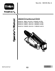
Form No. 3402-234 Rev A 2024 Directional Drill Model No. Model No. Model No. Model No. Register at www.Toro.com. Original Instructions (EN) 23800—Serial No. 313000001 and Up 23800A—Serial No. 314000001 and Up 23800C—Serial No. 314000001 and Up 23800W—Serial No.
You may contact Toro directly at www.Toro.com for product and accessory information, help finding a dealer, or to register your product. This product complies with all relevant European directives; for details, please see the separate product specific Declaration of Conformity (DOC) sheet. Whenever you need service, genuine Toro parts, or additional information, contact an Authorized Service Dealer or Toro Customer Service and have the model and serial numbers of your product ready.
Contents Priming the Fuel System ..........................................84 Replacing the Fuel Filters.........................................85 Checking Fuel Lines and Connections .......................86 Draining and Cleaning the Fuel Tank.........................86 Electrical System Maintenance ....................................86 Servicing the Battery...............................................86 Charging the Battery ...............................................87 Jump-starting the Machine..
Preparation Safety • Evaluate the terrain to determine what accessories and Improper use or maintenance by the operator or owner can result in injury. To reduce the potential for injury, comply with these safety instructions, and pay attention to the safety alert symbol , which means Caution, Warning, or Danger—“personal safety instruction.” Failure to comply with the instructions may result in personal injury or death. attachments are needed to properly and safely perform the job.
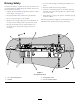
Driving Safety • Use care when loading or unloading the machine onto a You drive the machine to and from the work site with the use of a tethered remote. When driving the machine, observe the following safety precautions: • Watch for traffic when crossing roadways. trailer. • Check for overhead clearances (i.e. branches, doorways, electrical wires) before driving under any objects and do not contact them. • Operate the drive pendant alongside the machine outside of the danger zone (Figure 3).
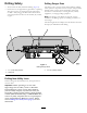
Drilling Safety Drilling Danger Zone • Always lower the safety bar before drilling (Figure 4). The danger zone is the area within and around the machine where a person is exposed to the risk of injury. This proximity includes where a person can be reached by operational movement of the machine, its working devices, auxiliary equipment, or swinging/falling equipment. • Ensure that no one approaches a pipe while it is spinning. The pipe can snag on clothing and cause amputation or death.
Utility Line Color Refer to the following table for the proper utility line and the corresponding utility line color (USA and Canada).
Maintenance and Storage – Do not refuel the machine indoors. • Do not touch parts which may be hot from operation. – Do not store the machine or fuel container inside where there is an open flame, such as near a water heater or furnace. Allow them to cool before attempting to maintain, adjust, or service. – Do not fill a container while it is inside a vehicle, trunk, pick-up bed, or any surface other than the ground. • Lower the thrust frame, stop the engine, and remove the key.
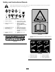
Safety and Instructional Decals Safety decals and instructions are easily visible to the operator and are located near any area of potential danger. Replace any decal that is damaged or lost. Battery Symbols Some or all of these symbols are on your battery 1. Explosion hazard 6. Keep bystanders a safe distance from the battery. 2. No fire, open flame, or smoking. 7. Wear eye protection; explosive gases can cause blindness and other injuries 3. Caustic liquid/chemical burn hazard 4.
125-6137 125-6108 1. Thrown object hazard—read the Operator’s Manual. 125-6694 125-6121 1. Engine—heating light 5. Fluid pump on 2. Engine—stop 6. Fluid pump off 3. Engine—run 7. Drill-pendant receptacle 4. Engine—start 8. Drive-pendant receptacle 1.
125-6119 125-8473 1. Explosion hazard—wear eye protection. 3. Fire hazard—keep open flames away. 2. Caustic liquid/chemical burn hazard—rinse affected area and seek medical assistance. 4. Poison hazard—do not tamper with the battery. 1. Entanglement hazard—keep away from moving objects. 125-6126 1. Entanglement hazard—keep away from moving parts. 125-6114 1. Stored energy hazard—do not use tools; read the Operator’s Manual.
5-6110 1. Crushing hazard—do not stand under any part of the machine. 125-6128 125-6131 1. High pressure fluid hazard, injection into the body—read the Operator’s Manual before performing maintenance. 1. Warning—stay at least 3 m (10 ft) away from the machine. 125-6115 1. Crushing hazard—deploy cylinder locks before performing maintenance. 125-6130 1. Warning—read the Operator’s Manual; stay at least 3 m (10 ft) away from the front and rear of the machine and 1.
125-6123 1. Load pipes from back row first. 125-6109 1. Electrical shock hazard—when the Zap-Alert system is activated by a power strike, do not leave the operator’s position or touch the ground and the machine at the same time; the machine will be energized with electrical power. 125-6124 1. Center the pipe joint between the upper and lower wrenches. 125-6111 1. Stake up 6. Stake up 2. Stake down 7. Stake spin counterclockwise 8. Stake down 3. Stake spin counterclockwise 4. Stake spin clockwise 5.
125-6140 1. Rotate the chair. 125-6107 1. Crushing hazard of hand and foot—keep hands and feet away. 125-6152 1. Move seat forwards and backwards. 125-6116 1. Falling hazard—do not move the machine when someone is in the operator’s position.
125-6112 1. Exit-side lockout—reset light 14. Work lights—Off 2. Exit-side lockout—drill-enabled light 15. Press and hold to increase engine speed. 3. Receiver-battery-status light 16. Engine speed 4. Engine—start 17. Press and hold to decrease engine speed. 5. Press down to stop the engine; pull up to start the engine. 18. Mode I—left trigger released, extends pipe gripper toward drill frame; left trigger pressed, opens lower wrench. Mode II—spin drill spindle clockwise. 6.
125-1645 1. Pull back drill carriage 6. Wrench controls on 2. Reverse left track 7. Drill spindle clockwise spin 3. Forward left track 8. Forward right track 4. Forward drill carriage 9. Reverse right track 5. Drill fluid pump on 10. Drill spindle counterclockwise spin 125-6125 1. Warning—read the Operator’s Manual. 2. Explosion hazard; electrical shock hazard—do not dig before calling local services. 3. Press to apply tread-joint compound. 4.
125-1622 1. Pull up to start the engine. 2. Push down to stop the engine. 125-6127 1. Cutting/dismemberment hazard, fan—keep away from moving parts. 125-6129 1. Hot surface—keep away from hot surfaces. 114-9600 1. Read the Operator's Manual.
Product Overview Figure 5 1. Drill carriage 6. Front hood 2. Zap-alert strobe 7. Right stabilizer 3. Operator seat 8. Rear hood 4. Control panel 9. Thrust frame 5.
Figure 6 1. Stake-down cage 5. Rear-control panel 2. Pipe holder 6. Left stabilizer 3. Safety bar 7. Stake-down plate 4.
Figure 7 4. Upper wrench 1. Thrust frame 2. Drill carriage 5. Lower wrench 3. Drill spindle 6.
Controls Operator-Controls Covers Refer to the following sections for the appropriate machine controls: The covers protect the operator controls from adverse weather conditions, such as rain, wind, sunlight, etc. Remove them before using the machine and replace them before leaving the machine for the day. Each cover is secured with 2 screws as shown in Figure 9.
Control-select Screen To release the platform and swing it out or in, press up on the front platform latch (Figure 11). When you power up the machine, this is the screen that appears after the start-up screen. The 2 control layouts that the operator can choose from consist of the following: • Mode I—Places the drilling functions on right joystick, while the left joystick operates the pipe loader and the wrench functions (Figure 13) Press button number 4 to select this function (Figure 13).
Machine-information Screen Main Operating Screen This screen contains the following information: To access this screen, press button 4 or the down arrow on the Machine-information Screen (page 23). • The machine model and serial number (Figure 14). The main operating screen displays the engine-rpm gauge, the fuel-quantity gauge, and the engine-temperature gauge (Figure 15). • The number of engine hours for the machine (Figure 14).
Main Drill Functions Displayed in Pressure Screen Main Drill Functions Displayed in Torque Screen To access this screen, press the down arrow on the Main Operating Screen (page 23). To access this screen, press the down arrow on the Main Drill Functions Displayed in Pressure Screen (page 24). This screen provides measurements on rotary pressure in psi, drilling-fluid pressure in psi, carriage pressure in psi, and drilling-fluid flow rate in gpm (Figure 16).
Drill-rotation-speed Screen Horsepower-control Screen To access this screen, simultaneously press the OK button and the left and right arrow buttons on the Main Operating Screen (page 23). The horsepower control allows the user to change the engine-speed (rpm) setting that the engine can droop to before the horsepower-control system can activate. This screen allows the user to increase or decrease the rotation speed of the drill.
Clear-service-reminder Screen To access this screen, press button number 4 as shown in Figure 20. 1 1 2 2 3 3 4 Enter PIN BACK ESC A 5 B 6 C 7 ENTER 8 OK g025094 Figure 22 Maintenance-cleared Screen Figure 20 Access-PIN Screen 1. Button number 4 (diagnose and update system) To clear a service reminder, enter the 8-digit PIN (16527316) into this screen (Figure 21): Figure 21 Enter-PIN Screen 1. Buttons for corresponding PIN numbers 2. PIN entry appears here 3. Enter PIN 4.
Lubrication and Maintenance Screens These screens provide the user with maintenance schedules at 10-hour, 50-hour, 250-hour, 500-hour, and 1,000-hour increments. Note: Press the OK button to exit this screen.
Error Codes Screen The following figure is an example of how an error code appears. This screen displays the number of drill errors that have occurred. Notice that the text before the occurrence count entails what the actual error is. If more than 1 drill error is shown on the screen, press button 6 to see the next drilling error (Figure 28). Note: If there are no drilling errors, press the OK button to exit this screen (Figure 28). Figure 30 1. Number of errors and number of reset errors 2.
Rotary and Carriage-service Screen Auxiliary-activations Screen From the Main Operating Screen (page 23), press button numbers 1 and 5 simultaneously to access this screen. Press the down arrow on the Rotary and Carriage-service Screen (page 29) to access this screen.
Drilling-fluid-information Screen Track-drive-information Screen Press the down arrow on the Auxiliary-activations Screen (page 29) to access this screen. Press the down arrow on the Drilling-fluid-information Screen (page 30) to access this screen.
Control Panel Engine-Start Button Press this button (Figure 36) to start the engine. The key switch on the rear, control panel must be in the ON position. Engine-Stop Button 1 2 3 6 Press this button (Figure 36) to immediately stop the engine and all drilling operations. You must pull this button out before you can start the engine again.
Left Joystick—Mode I Front Button Note: The joystick controls vary depending on the control mode you select when powering up the machine. There are 2 control modes: Mode I and Mode II; refer to the Control-Select Screen in the Software Guide for information on setting the control mode. • Left trigger pressed—press this button to resume the 1 previously set auto-drill speed. Press and hold this button to increase the auto-drill speed. • Left trigger released—press this button to close the pipe gripper.
Left Joystick—Mode II Front Button Note: The joystick controls vary depending on the control mode you select when powering up the machine. There are 2 control modes: Mode I and Mode II; refer to the Control-Select Screen in the Software Guide for information on setting the control mode. • Left trigger pressed—press this button to resume the 1 previously set auto-drill speed. Press and hold this button to increase the auto-drill speed.
Right Joystick—Mode I Lower Button Note: The joystick controls vary depending on the control mode you select when powering up the machine. There are 2 control modes: Mode I and Mode II; refer to the Control-Select Screen in the Software Guide for information on setting the control mode. Press this button to turn the drilling-fluid pump on or off. 1 Trigger Press and hold the trigger to move the drill carriage at high speed up or down the drill frame.
Right Joystick—Mode II Lower Button Note: The joystick controls vary depending on the control mode you select when powering up the machine. There are 2 control modes: Mode I and Mode II; refer to Control-Select Screen in the Software Guide for information on setting the control mode. Press this button to turn the drilling-fluid pump on or off. 1 Trigger Press and hold the trigger to move the drill carriage at high speed up or down the drill frame.
Exit-Side-Lockout System (Standard Range) Engine, Key Switch The key switch has 3 positions as follows (Figure 42): The exit-side-lockout system provides the individuals working around the machine with a means to disable the drill pipe from rotating and thrusting. 1 2 For more information and instructions, refer to the Operator’s Manual for the Exit-side-lockout system.
Drive Pendant Drill Frame and Stabilizer Controls Refer to Figure 41 for location. 1 2 3 1 3 2 4 5 g021843 Figure 43 1. Drill-frame tilt lever 3. Right-stabilizer lever 2. Left-stabilizer lever g021855 Figure 44 Stabilizer Levers Use the stabilizer levers to raise and lower the stabilizers. Note: The DRIVE/DRILL switch on the operator panel must be switched to the DRIVE position for this function to work. 1. Engine-speed switch 4. Drive-speed switch 2. Drive-direction joystick 5.
Drive-Speed Switch Left Switch The switch sets the speed at which the machine will travel. Move the switch up for high speed or down for low speed. • When connected to the drill-pendant receptacle, move Operator-Presence Switch • When connected to the drive-pendant receptacle, move this switch up to move the drill carriage forward or down to move the drill carriage rearward. this switch up to move the left track forward or down to move the left track rearward.
Battery-Disconnect Switch Specifications Open the front hood to access the BATTERY -DISCONNECT switch; refer to Opening the Front Hood (page 72). Note: Specifications and design are subject to change without notice. The BATTERY -DISCONNECT switch is located to the right of the engine; it is used to electrically disconnect the battery from the machine. Machine Turn the BATTERY -DISCONNECT switch to the ON or OFF position to perform the following: Width 131 cm (51.
Operation Refer to Preparing the Job Site and the Machine (page 52) for instructions on preparing the job site and the machine. Note: Determine the left and right sides of the machine from the normal operating position. 4. Drill the bore. You drill the bore in three stages: Understanding Horizontal Directional Drilling A. Entry In the entry phase of the bore, you push the drill bit and head into the ground at an angle of up to 16 degrees.
Gathering Site Information DANGER Contacting underground hazards with the machine while drilling or reaming can cause explosion, electrocution, breathing problems, severe trauma, and death to you or bystanders. Planning the Initial Route Before you can begin boring, you need to plan the route you will bore and prepare as follows: – Ensure that all personnel at the job site wear personal protective equipment including a hard hat, eye protection, and hearing protection.
– Electrical power lines – Crystalline silica and other dust If you will be drilling through or cutting concrete, sand, or other substances that create dusts or fumes, you need to ensure that you and all workers wear breathing protection to protect your lungs from the dust. DANGER Drilling into an electric power line will cause the machine to become electrified and may electrocute you or any bystanders. ◊ Keep bystanders and spectators away from the job site, including the complete bore path.
Planning the Bore Path Before setting up the job site, you need to plan the bore path, including the following: 1 4 3 2 5 g021764 Figure 48 1. Bore entry 4. Obstacle 2. Beginning-of-bore-at-depth point 5. End-of-bore-at-depth point and bore exit 3. Bore depth • Bore entry needed for steering the drill to the surface, typically 9 to 15 m (30 to 50 ft) from the end-of-the-bore-at-depth point. The is the location where you setup the machine and the drill bit enters the ground.
1 g021765 Figure 49 1. 20 cm (8 inches) This flexibility is often rated in materials as a minimum bend radius, which is the radius of the circle formed if the material or pipes, connected together, were bent to form a giant circle. The minimum radius of a circle made with the pipe used with this machine is 36.6 m (102 ft). 1 2 • Entry pitch g021767 The entry pitch is the angle at which the machine enters the ground.
Note: The depths given in the following table are for 3 m (10 ft) of combined drill head and pipe. As you steer up, the pitch of the steered section will change and can be monitored with the receiver. Use the following table to identify how many lengths of pipe will be necessary to insert and steer to the beginning point and help you choose an entry point.
Given the above information, you can calculate the number of rods required to reach your beginning point at the appropriate depth. Toro recommends that you start the entry point a distance back from your beginning-at-depth point by the same distance as the length of pipes you will need to reach that point. This will ensure that you have enough extra space so you will not need to over-steer and damage the pipes.
• You insert the first 3 m (10 ft) of drill bit/pipe into the The following example illustrates the process given an installation using the machine at an 18% pitch on level ground: ground with no steering. The end of the drill bit will be 53 cm (21 inches) deep (Figure 53). 6 1 2 3 4 5 g021769 Figure 53 1. 18% pitch 3. 96 cm (38 inches 5. 119 cm (47 inches) 2. 53 cm (21 inches) 4. 114 cm (45 inches) 6. 10.
Understanding and Using the Exit-side-lockout System (Standard Range) Understanding and Using the Handheld Transmitter (Standard Range) The individual holding the transmitter can push the Lock Drill (Off) button to stop the drill rotation and thrust.
8. Release the On button. The Red light turns off and the Green light flashes for a few seconds. Disassociating all Handheld Transmitters from the Base Unit (Standard Range) Important: Completing this procedure will disassociate all transmitters from the base unit, which will need to be associated again before they will function. 1. Ensure that the machine is turned off. 2. Ensure that the handheld transmitter is not active (i.e., no lights are on). Figure 57 1. Handheld transmitter 2. AAA batteries 3.
Understanding and Using the Exit-side-lockout System (Long Range) Indicator Light Understanding the Base-unit Transmitter Indicator Lights (Long Range) The following table lists the various states of the indicator lights on the base-unit transmitter (Figure 58) and their meanings: Figure 58 1. Polarity-reversal indicator 2. 3. 4. 5. 6. +V1 +V2 +V3 RTX RRX 7. Over temperature/voltage 8. 9. 10. 11. 12.
Understanding and Using the Handheld Transmitter Indicator Lights (Long Range) Meaning Indicator Light State The individual holding the transmitter can push the Lock Drill (Off) button to stop the drill rotation and thrust.
Preparing the Job Site and the Machine Important: Ensure that you install the batteries in the correct polarity orientation or you could damage the transmitter. Before drilling, prepare the job site and machine as follows: • Mark and prepare the bore path Marking and Preparing the Bore Path (page 52). • Test the Zap-Alert system; refer to Testing the Zap-Alert System (page 53). • Load the drill pipes into the pipe holder if needed; refer to Loading Drill Pipes into the Pipe Holder (page 55).
Testing the Zap-Alert System The Zap-Alert system is an electric strike sensing device on the machine that triggers a strobe light and audible alarm in the event that the drill bit, reamer, or stake breaks into an energized power line. In the event of an electric strike, the machine will become energized, setting off the alarm. DANGER If the Zap-Alert system activates while drilling, the machine, except for the operator’s platform, will become energized.
7. Disconnect the alligator clips from the grounding stud and the machine. 8. Store the grounding stake in the holder on the operator platform as shown in Figure 64. 1 g021838 Figure 64 1. Grounding stake If either the audible alarm or the strobe light failed to trigger when you pressed the test button, have them repaired before drilling with the machine. Mounting a Fire Extinguisher Mount your fire extinguisher below the operator seat (Figure 65).
Loading Drill Pipes into the Pipe Holder Before using the machine, fill the pipe holder with up to 40 drill pipes. Figure 66 1. Pipe 2. Male end 3. Clevis pins Adding Fuel 1. Remove the clevis pins from the pipe holder (Figure 66). Service Interval: Before each use or daily—Check the fuel level. 2. Insert the pipes from the top with the male threaded pipe ends toward the front of the machine (Figure 66).
Use of summer grade fuel above -7° C (20° F) will contribute toward longer fuel pump life and increased power compared to winter grade fuel. • If this is not possible, then refuel such equipment on Important: Do not use kerosene or gasoline instead of diesel fuel. Failure to observe this caution will damage the engine. • If a fuel dispenser nozzle must be used, keep the nozzle in a truck or trailer from a portable container, rather than from a fuel dispenser nozzle.
Adjusting the Carriage Pressure Checking the Engine-oil Level To hydraulically adjust the carriage pressure, do the following: Before you start the engine and use the machine, check the oil level in the engine crankcase; refer to Checking the Engine-oil Level (page 81) in Engine Maintenance. 1. Press button 7 on the screen to turn the carriage pressure to the On position (green), as shown in Figure 68.
Loading and Unloading the Machine 4. Using the drive pendant, set the engine speed to slow and the drive speed to slow. WARNING 5. Using the drive pendant, carefully drive the machine forward or rearward up the ramp and into position on the trailer. Moving a machine of this size on a trailer over public roads carries risks to those around the machine if it should come loose, be involved in an accident, hit a low hanging structure, etc. 6. Lower the stake-down plate to the deck of the trailer. 7.
Drill bits vary in size and type to meet the various soil conditions you may need to drill through. Some of the possibilities are as follows: • Straight blade—Used in a wide range of medium density soils. • Bent blade—Used in medium to soft soils. This bit has an added 20° bend to increase steering performance in soft soils. Figure 74 • Triangle point blade—Use in hard and rocky soils. This bit has carbide edges to reduce wear. 1. Sonde housing 3. Drill bit 2.
Setting up the Machine for Drilling Note: The operator platform has 4 positions: travel (swung all the way into the machine), full-out, and 2 intermediate positions. 1. Using the drive pendant, drive the machine to the location that you have prepared for it, ensuring that the front of the machine is the proper distance back from entry point and the drill frame is in line with the bore path. 2. Drive up to the location and make sure that all utilities are located and marked prior to drilling. 3.
Connecting to a Drilling-fluid Source When drilling and reaming, you pump a mixture of bentonite clay, water, and sometimes other ingredients, collectively called drilling fluid or “Mud”, through the pipe and into the bore. This drilling fluid, or “Mud”, does the following for your bore: • Lubricates the drill head • Loosens the soil into which the drill is cutting • Penetrates and binds loose soil to keep them from collapsing on the bore pipe.
Setting Up the Pump to Use a Natural Water Source Deploying the Zap-Alert System To set up a pump to use a natural water source, you must ensure that you use the Y-screen to filter all materials other than water. The Zap-Alert system is an electric strike sensing device on the machine that triggers a strobe light and audible alarm in the event that the drill bit, reamer, or stake breaks into an energized power line.
4. Lower the pipe elevators to load a pipe into the pipe gripper. 1 5. Rotate the pipe gripper with the pipe toward the drill frame, and extend the pipe until the pipe is centered over the frame and in front of the spindle on the drill carriage. 6. Rotate the drill spindle clockwise and move the carriage slowly forward to insert the spindle into the female end of the pipe (Figure 85). g021838 Figure 83 1. Grounding stake 2.
Installing the Drill Head 5. Using the upper wrench, clamp the lead bar and tighten it to full machine torque. 1. Using the exit-side-lockout transmitter, enable the exit side lockout. 6. Using the exit-side-lockout transmitter, enable the exit-side lockout. WARNING 7. Double check the drill head and bit to ensure that the fluid ports are clean and free from obstructions.
Note: This will allow the carriage to float, and will not damage the pipe threads. transmitter temperature, and orientation in the soil. The remote console is a screen that remains near you (the drill operator) to show you the information from the receiver while drilling so you can make steering decisions. 4. Rotate the drill head counterclockwise until the spindle is completely removed from the pipe.
Exiting the Ground Backreaming and Pullback As you approach the end of the bore, steer the drill head to the exit point, keeping the steering limits in mind as you do so. Before exiting the ground, ensure that everyone is away from the exit point. As soon as you break through, stop the drilling-fluid flow. Extend the drill forward until the entire drill head is out of the ground. After drilling the initial bore, you attach a reamer to the pipe which is then connected to a the product you are installing.
Removing Drill Pipes 13. Move the drill carriage back until the male-pipe threads just clear the female end of the lower pipe, then close the upper wrench onto the pipe end, but not on the threads. 1. Using the exit-side-lockout transmitter, enable the exit side lockout. 2. Install a drill-pipe wiper around the pipe and into the retaining bracket on the front of the machine. 14. Rotate the drill spindle counterclockwise until the upper-pipe joint is loose but not separated.
6. Leave the lead bar clamped in the lower wrench, but do not connect the drill spindle to the lead bar. Using the TJC Applicator 7. Remove the reamer from the end of the lead bar as directed by the reamer manufacturer. Adjusting the Applicator Nozzle You can adjust the applicator nozzle to spray thread-joint compound (TJC) either in a fan-shaped spray or as a stream. 8. Release the lower wrench and pull the lead bar out of the pipe guide.
Adjusting the TJC-spray Volume Filling the TJC Applicator 1. Stop the machine and stop the engine. To adjust the volume of thread-joint compound that is delivered by the applicator, complete the following: 2. Open the stake-down-guard door. 1. Loosen the jam nut on the adjustment bolt located on top of the TJC-applicator piston (Figure 90). 1 2 3. Loosen the wing nuts securing the cover straps to the machine (Figure 91). 3 1 2 3 4 5 g021846 g021845 Figure 91 Figure 90 1. Adjustment bolt 3.
Moving a Disabled Machine Whenever the machine is stopped and the engine is not running, the hydrostatic brakes automatically engage. Do not attempt to tow the machine if it cannot move under its own power. If possible, repair the machine at the site. If this is not possible, use a crane and a spreader bar to lift the machine onto a trailer, using the lift points shown in Figure 92. Figure 92 Repeat lift points on other side 1. Spreader bar 2.
Maintenance Note: Determine the left and right sides of the machine from the normal operating position. Recommended Maintenance Schedule(s) Maintenance Service Interval Maintenance Procedure After the first 100 hours • Check the gearbox drive oil. • Change the gearbox-drive oil. After the first 250 hours • Adjust the valve clearance. • Change the planetary oil. Before each use or daily • • • • • • • • • • Check the fuel level. Grease the machine. (Grease immediately after every washing).
CAUTION If you leave the key in the ignition switch, someone could accidently start the engine and seriously injure you or other bystanders. Remove the key from the ignition before you do any maintenance. WARNING Improperly servicing or repairing the machine may cause injury or death. If you do not understand the service procedures for this machine, contact your dealer or see the service manual for this machine. WARNING Raised equipment on the machine without an operator may cause injury or death.
Opening the Rear Hood 3. Lift up the handle as shown in Figure 96. 1. Park the machine on a level surface, stop the engine, and remove the ignition key. 2. Pull the hood latch out (Figure 95). Figure 96 1. Hood handle Figure 95 1.
Removing and Storing the Cylinder Lock Using the Cylinder Lock WARNING 1. Start the engine. The thrust frame may lower when it is in the raised position, causing serious injury or death. 2. Lower the thrust frame to the fully lowered position. 3. Stop the engine. Install the cylinder lock before performing maintenance that requires the thrust frame to be raised. 4. Remove the cotter pin and the clevis pin that secure the cylinder lock (Figure 97). 5. Remove the cylinder lock. 6.
Lubrication Greasing the Machine Service Interval: Before each use or daily (Grease immediately after every washing). Grease type: General-purpose grease. 1. Park the machine on a level surface, stop the engine, and remove the ignition key. 2. Clean the grease fittings with a rag. 3. Connect a grease gun to each fitting. 4. Pump grease into the fittings until grease begins to ooze out of the bearings (approximately 3 pumps). 5. Wipe up any excess grease.
Figure 104 Rear-pipe elevator (operator’s side) Figure 107 Carriage-roller bearings (operator’s side shown; repeat on other side) Figure 105 Front-pipe elevator (operator’s side) Figure 108 Gearbox float (operator’s side shown; repeat on other side) Figure 106 Stakedown motors 76
Figure 109 Track roller (operator’s side shown; repeat on other side) Engine Maintenance Cleaning the Crankcase-vent Tube Service Interval: Before each use or daily—Check the crankcase-vent tube and clean it if necessary. 1. Park the machine on a level surface, stop the engine, and remove the ignition key. Figure 110 Rear-cam bearing (operator’s side) 2. Open the front hood; refer to Opening the Front Hood (page 72). 3. Gently pull the crankcase-vent tube out (Figure 112). 4.
Servicing the Air-cleaning System B. Important: Do not remove the elements from the machine to check for dirty filters; use the following procedure instead. Repeat steps 1 and 2; if the restricted air-cleaner indicator is still shown on the display screen, replace the secondary, air-cleaner filter; refer to Servicing the Air-cleaner Filter (page 80).
Installing the Air-cleaner Cover 3. Clean the outside of the air-cleaner canister with a clean, damp cloth. 1. Park the machine on a level surface, stop the engine, and remove the ignition key. 4. Check the air-cleaner canister for damage which could cause an air leak. Replace a damaged air cleaner body. 2. Align the dust cap on the air cleaner filter cover to the 5 o’clock position. Important: Service the air-cleaner filter only when “Check Air Filter” is displayed on the screen.
Servicing the Air-cleaner Filter Service Interval: Every 250 hours Replace the filters only when the “Check Air Filter” indicator appears on the display screen; refer to Checking the Air-cleaner Indicator (page 78). Note: Contact your Authorized Toro Dealer to order replacement filters. 1. Park the machine on a level surface, stop the engine, and remove the ignition key. 2. Open the front hood; refer to Opening the Front Hood (page 72). Figure 118 1. Safety filter 3.
of low viscosity oil can decrease engine life because of wear (Figure 119). Toro Premium Engine Oil is available from an Authorized Toro Service Dealer in either 15W-40 or 10W-30 viscosity with API classification CH-4 or higher. See the parts catalog for part numbers. Checking the Engine-oil Level G021582 Service Interval: Before each use or daily—Check the engine-oil level. 1. Park the machine on a level surface, stop the engine, and remove the ignition key. 1 2.
7. Apply a thin layer of the specified-engine oil to the seal of the oil filter. 8. Align the oil filter to the oil-filter adapter and rotate it clockwise until the seal of the oil filter contacts the oil-filter adapter (Figure 122). Note: Do not use an oil filter strap wrench to install the new oil filter. The wrench can dent an oil filter and therefore cause a leak. 9. Hand tighten the oil filter an additional 1/2 turn (Figure 122). Figure 124 10.
Servicing the Spark Arrestor (If Equipped) Fuel System Maintenance Service Interval: Every 250 hours—Clear the spark arrestor in the muffler of carbon buildup. DANGER 1. Park the machine on a level surface, stop the engine, and remove the ignition key. Under certain conditions, diesel fuel and fuel vapors are highly flammable and explosive. A fire or explosion from fuel can burn you and others and can cause property damage.
Priming the Fuel System and drain any water and sediment from the fuel filter (Figure 125). Note: Prime the fuel system whenever any of the following occur: Note: If the fuel-water separator has any water or sediment, also drain the water and sediment from the fuel tank; refer to Draining Water from the Fuel Tank (page 84). • You drained water from the fuel filter. • You replaced the fuel filter. 5. When clean fuel appears, rotate the drain valve clockwise until it is closed.
WARNING The fuel system is under high pressure. Bleeding the system without proper precautions and training could result in injury to you from injected fluid or fire or explosion. Read the engine owner’s manual for the proper bleeding procedure or contact your Authorized Toro Dealer. Replacing the Fuel Filters Service Interval: Every 250 hours—Replace the primary and secondary, fuel filters. Replacing the Primary, Fuel Filter 1.
Checking Fuel Lines and Connections Electrical System Maintenance Service Interval: Every 500 hours/Yearly (whichever comes first)—Inspect the fuel lines and connections. Servicing the Battery Inspect the fuel lines and connections for deterioration, damage, or loose connections.
Charging the Battery WARNING A battery contains sulfuric acid, which can cause serious burns; and they can produce explosive gases. WARNING Charging the battery produces gasses that can explode. • Avoid contact with skin, eyes, or clothing; flush affected areas with water. Do not smoke near the battery and keep sparks and flames away from battery. • If taken internally, drink large quantities of water or milk. Do not induce vomiting. Seek medical attention immediately.
Battery-charger Table Charger setting Charging time 4 to 6 amperes 30 minutes 25 to 30 amperes 10 to 15 minutes 8. When the battery is fully charged, unplug the charger from the electrical source, then disconnect the charger leads from the battery posts (Figure 129). Jump-starting the Machine WARNING Figure 130 Jump-starting the battery can produce gasses that can explode. Do not smoke near the battery and keep sparks and flames away from battery. 1. Jumper-cable clamp (positive) 4.
Changing the Oil for the Planetary Drive Drive System Maintenance Service Interval: After the first 250 hours—Change the planetary oil. Checking the Oil Level for the Planetary Drive Every 800 hours—Change the planetary oil (or yearly, whichever comes first). Note: Change the oil when it is warm, if possible. Service Interval: Every 50 hours—Check the planetary-drive oil level (Also, check if external leakage is observed). 1. Park the machine on a level surface. 2.
Figure 132 1. Sight-glass 3. Remove the breather cap and add the oil into the gearbox drive until the oil level on the sight-glass is at least half full (Figure 132). Figure 133 Changing the Oil for the Gearbox Drive 2. Stop the engine and remove the ignition key. 3. Remove the 4 bolts on the guard plate and gearbox (Box A of Figure 133). Service Interval: After the first 100 hours—Change the gearbox-drive oil. 4. Remove the guard plate (Box A of Figure 133).
9. Place the guard back into place and install the 2 bolts (Box A of Figure 133). 5. Remove excess grease from around the valve. 6. Install the cover and retaining bolts. 10. Install the 2 other bolts securing the lid onto the gearbox (Box A of Figure 133). 7. Repeat steps 2 through 6 to tighten the track tension on the other side. 11. Torque the bolts to 23 to 29 N∙m (17 to 21 ft-lb).
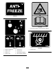
Checking the Coolant Level in the Reservoir Cooling System Maintenance Service Interval: Before each use or daily Coolant specification: 50/50 solution of ethylene-glycol antifreeze and water or equivalent Important: Do not remove the radiator filler cap during this procedure. Engine and Radiator coolant capacity: 16.77 L (17.7 US qt) 1. Park the machine on a level surface, stop the engine, and remove the ignition key. 2. Allow the engine to cool.
Checking the Concentration of the Coolant Note: The cooling system is filled with a 50/50 solution of water and ethylene-glycol antifreeze. 1. Park the machine on a level surface, stop the engine, and remove the ignition key. 2. Allow the engine to cool. 3. Open the front hood and rear hood; refer to Opening the Front Hood (page 72) and Opening the Rear Hood (page 73). 4.
6. Open the drain plug for the radiator and allow the coolant system to drain completely. E. Open the drain plug for the radiator, and drain the cleaning solution into a drain pan. Note: Dispose of the used coolant properly according to local codes. 7. Clean the threads on the drain plug and apply 3 layers of PTFE sealing tape. F. Clean the threads on the drain plug and apply 3 layers of PTFE sealing tape. G. Close the drain plug. 3. Flush the cooling system as follows: 8.
Belt Maintenance Filling the System with Coolant Important: You must fill the cooling system properly to prevent air locks in the cooling passages. Failing to vent the cooling system properly can severely damage the cooling system and engine. Servicing the Engine-drive Belt Important: Use a mixture of 50% ethylene glycol and 50% water mixture or equivalent in the machine. The lowest ambient operating temperature for this mixture is above -37° C (-34° F).
Adjusting the Tension of the Belt Checking the Tension of the Belt 1. Park the machine on a level surface, stop the engine, and remove the ignition key. Service Interval: Every 1,000 hours 1. Park the machine on a level surface, stop the engine, and remove the ignition key. 2. Open the front hood; refer to Opening the Front Hood (page 72). 2. Open the front hood; refer to Opening the Front Hood (page 72). 3. Loosen the nut and bolt at the pivot point for the alternator (Figure 143). 3.
Checking the Hydraulic Fluid Hydraulic System Maintenance Service Interval: Before each use or daily Check the hydraulic fluid as follows: Servicing the Hydraulic Fluid 1. Park the machine on a level surface, stop the engine, and remove the ignition key. The hydraulic reservoir is filled at the factory with approximately 102 L (27 US gallons) of high-quality hydraulic fluid. Check the level of the hydraulic fluid before the engine is first started and daily thereafter.
Changing the Hydraulic-fluid Return Filter Changing the Hydraulic-pressure Filter Service Interval: Every 500 hours/Every 6 months (whichever comes first) Service Interval: Every 500 hours/Every 6 months (whichever comes first) 1. Park the machine on a level surface, stop the engine, and remove the ignition key. 1. Park the machine on a level surface, stop the engine, and remove the ignition key. 2. Open the front hood; refer to Opening the Front Hood (page 72). 2.
Inspect the hydraulic lines and hoses daily for leaks, kinked lines, loose mounting supports, wear, loose fittings, weather deterioration, and chemical deterioration. Make all necessary repairs before operating. WARNING Raising the rear of the unit relying solely on mechanical or hydraulic jacks could be dangerous. The mechanical or hydraulic jacks may not be enough support or may malfunction allowing the unit to fall, which could cause injury or death.
Drilling-fluid Pump Maintenance 4. Ensure that the oil is at the oil-fill line as shown in Figure 147. Note: If the oil is below the oil-fill line, refer to step 8 of Changing the Drilling-fluid Pump Oil (page 100) and add the necessary amount of oil. Servicing the Drilling-fluid-pump Oil Changing the Drilling-fluid Pump Oil The drilling-fluid pump is shipped with oil in the crankcase; however, check the oil level before and after you first start the engine.
Preparing the Drilling-fluid System for Cold Weather 1 Prepare the machine as follows after drilling if the temperature will be below 0° C (32° F). 1. Park the machine on a level surface, stop the engine, and remove the ignition key. 2. Prepare the machine to circulate the antifreeze as follows: A. Open the rear hood; refer to Opening the Rear Hood (page 73). B. G022141 Place a drain pan under the drill spindle for the leaked antifreeze (Figure 149). 2 Figure 151 1 1. Antifreeze-tank cap 2.
Cleaning Cleaning with the Spray-hose Attachment Service Interval: Before each use or daily The machine comes with a spray-hose attachment that you can use to clean the machine and pipes. Figure 154 Important: Do not spray any electronic component of the machine and ensure that the hood is down before cleaning the machine with the spray-hose attachment. 1.
Storage 7. Turn the drilling-fluid pump to the On position through the display screen; refer to Main Drill Functions Displayed in Pressure Screen (page 24). 1. Stop the engine and remove the key. 8. Using the spray-hose attachment, hold down the lever and spray down the machine and pipes. 2. Remove dirt and grime from the entire machine. Important: You can wash the machine with mild detergent and water. Avoid excessive use of water, especially near the control panel, engine, hydraulic pumps, and motors.
Troubleshooting Problem The starter does not crank. The engine cranks, but will not start. Possible Cause Corrective Action 1. The battery-disconnect switch is in the Off position. 1. Turn the battery-disconnect switch to the On position. 2. The electrical connections are corroded or loose. 3. A fuse is blown or loose. 4. The battery is discharged. 5. The relay or switch is damaged. 6. A starter or starter solenoid is damaged. 7. The internal engine components have seized. 2.
Problem The engine starts, but does not keep running. Possible Cause 1. The fuel tank vent is restricted. 1. Loosen the cap. If the engine runs with the cap loosened, replace the cap. 2. Dirt or water is in the fuel system. 2. Drain and flush the fuel system; add fresh fuel. 3. Replace the fuel filter. 4. Bleed the nozzles and check for air leaks at fuel hose connections and fittings between the fuel tank and engine. 5. Drain the fuel system and replace the fuel filter.
Problem The engine overheats. Possible Cause 1. More coolant is needed. 1. Check and add coolant. 2. There is restricted air flow to the radiator. 3. The crankcase oil level is incorrect. 4. There is excessive loading. 2. Inspect and clean the side panel screens with every use. 3. Fill or drain to the full mark. 4. Reduce the load and use a lower ground speed. 5. Drain and flush the fuel system; add fresh fuel. 6. Contact your Authorized Service Dealer. 7. Contact your Authorized Service Dealer. 8.
Index 811 ............................. 4, 40–41 A Accessories. . . . . . . . . . . . . . . . . . . . . . . . . . . . . . . . 39 Adding drill pipes . . . . . . . . . . . . . . . . . . . . . . . . . . 64 Adding fuel. . . . . . . . . . . . . . . . . . . . . . . . . . . . . . . . . 55 Air-cleaning system Checking the air-cleaner indicator. . . . . 80 Cleaning the dust valve . . . . . . . . . . . . . . . . 78 Cover latch . . . . . . . . . . . . . . . . . . . . . . . . . . . . . . 78 Installing the cover. . . .
Horizontal shaft . . . . . . . . . . . . . . . . . . . . . . . . . 65 Setting up . . . . . . . . . . . . . . . . . . . . . . . . . . . . . . . 60 Starting the first pipe . . . . . . . . . . . . . . . . . . . 63 Steering . . . . . . . . . . . . . . . . . . . . . . . . . . . . . . . . . 65 Drilling danger zone. . . . . . . . . . . . . . . . . . . . . . . . .6 Drilling fluid Pump Changing the oil . . . . . . . . . . . . . . . . . . . . . 100 Checking the oil level . . . . . . . . . . . . . . .
Left joystick Location . . . . . . . . . . . . . . . . . . . . . . . . . . . . . . . . . 21 Mode I . . . . . . . . . . . . . . . . . . . . . . . . . . . . . . . . . . . 32 Mode II . . . . . . . . . . . . . . . . . . . . . . . . . . . . . . . . . . 33 Left-stabilizer lever . . . . . . . . . . . . . . . . . . . . . . . . 37 Length. . . . . . . . . . . . . . . . . . . . . . . . . . . . . . . . . . . . . . 39 Lever Drill-frame tilt . . . . . . . . . . . . . . . . . . . . . . . . . . . . 37 Left-stabilizer. . .
Location. . . . . . . . . . . . . . . . . . . . . . . . . . . . . . . 19 R Reamer Carbide step-wing cutter . . . . . . . . . . . . . . . 66 Cast cone packer . . . . . . . . . . . . . . . . . . . . . . . 66 Connecting . . . . . . . . . . . . . . . . . . . . . . . . . . . . . . 66 Fluted . . . . . . . . . . . . . . . . . . . . . . . . . . . . . . . . . . . . 66 Removing . . . . . . . . . . . . . . . . . . . . . . . . . . . . . . . 67 Rear button Left joystick. . . . . . . . . . . . . . . . . . . . . . . . . .
Vent tube Cleaning . . . . . . . . . . . . . . . . . . . . . . . . . . . . . . . . . 77 Vibration information . . . . . . . . . . . . . . . . . . . . . . . .8 W Water as drilling fluid. . . . . . . . . . . . . . . . . . . . . . 62 Water lines Safety precautions. . . . . . . . . . . . . . . . . . . . . . . .7 Weight. . . . . . . . . . . . . . . . . . . . . . . . . . . . . . . . . . . . . . 39 Width . . . . . . . . . . . . . . . . . . . . . . . . . . . . . . . . . . . . . . . 39 Wiper Pipe . . . . . . . . . .
Underground Equipment The Toro Underground Warranty A Limited Warranty Conditions and Products Covered The Toro Company and its affiliate, Toro Warranty Company, pursuant to an agreement between them, jointly warrant your Toro Underground Equipment (“Product”) to be free from defects in materials or workmanship. Where a warrantable condition exists, we will repair the Product at no cost to you including diagnostics, labor, and parts.