
Installation Instructions

InstallingtheRockStakesonthe2024
DirectionalDrill
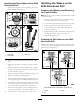
1.Securethestakeguideontotheguideringusingthe8
bolts(M8)(BoxAofFigure4).
Figure4
1.Bolts(M8)3.Guidering
2.Stakeguide
2.Placetheassemblyintotheholeofthethrustframe
foot.
3.Aligntheboltheadssothattheyaresquarewiththe
foot.
4.Weldtheguideringontothemachineusing7equally
spaced5cmby0.64cm(2inchby0.25inch)weldsas
showninBoxBofFigure4.
5.Removetheboltsandstakeguide(BoxCofFigure4).
6.Painttheweldedareawithblackpaint.
7.Placethestakeguideonthestakeandguidethestake
intotheguideringonthemachine(BoxDofFigure4).
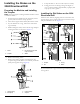
8.Installthenewstakesbyaligningtheholeinthestake
withtheholeinthemotorcouplerandsecureitwith
theO-ringsandpinsincludedinthiskit(Figure3).
9.Securethestake-guideringontheweldedguidering
usingthe8bolts(M8-11/4x20mm)(Figure4).
10.Torquetheboltsto23to29N-m(17to21ft-lb).
InstallingtheStakesonthe
4045DirectionalDrill
PreparingtheMachineandRemoving
theCurrentStakes
Note:Having2peopleoraliftingmechanismmakesiteasier
toinstallthestakes.
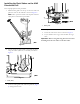
1.Positionthethrustframe25.4cm(12inches)offthe
ground,withthestakesintheupposition.
2.Turnofftheengineandthebatterydisconnectswitch.
3.Supportthefootwithajackstandorequivalent.
4.Ifyourmachinehasacage,unlatchandopenthe
stake-downcagedoor.
5.Whileholdingthestakes,removethepinsande-clips
securingthestakestothemotors(Figure1).
6.Removetheexistingstakes.
InstallingtheDirtStakesonthe4045
DirectionalDrill
Installthenewstakesbyaligningtheholeinthestakewith
theholeinthemotorandsecureitwiththepinsande-clips
previouslyremoved(Figure5).
Figure5
Rockstakesshownforillustrativepurposesonly
1.Coupler3.Stake
2.Pin
3