Form No. 3401-814 Rev A 4045 Directional Drill Model No. Model No. Model No. Model No. Model No. Model No. Model No. Model No. Model No. Model No. Register at www.Toro.com. Original Instructions (EN) 23823—Serial No. 315000001 and Up 23823A—Serial No. 315000001 and Up 23823C—Serial No. 315000001 and Up 23823TE—Serial No. 315000001 and Up 23823W—Serial No. 315000001 and Up 23825—Serial No. 315000001 and Up 23825A—Serial No. 315000001 and Up 23825C—Serial No. 315000001 and Up 23825TE—Serial No.
Read this information carefully to learn how to operate and maintain your product properly and to avoid injury and product damage. You are responsible for operating the product properly and safely. This product complies with all relevant European directives; for details, please see the separate product specific Declaration of Conformity (DOC) sheet. WARNING You may contact Toro directly at www.Toro.
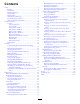
Contents Draining Water from the Fuel Tank ...........................74 Priming the Fuel System ..........................................75 Replacing the Fuel Filters.........................................75 Checking the Fuel Lines and Connections ..................76 Draining and Cleaning the Fuel Tank.........................76 Electrical System Maintenance ....................................77 Servicing the Battery...............................................77 Charging the Battery ..............
Preparation Safety • Evaluate the terrain to determine what accessories and Improper use or maintenance by the operator or owner can result in injury. To reduce the potential for injury, comply with these safety instructions, and pay attention to the safety alert symbol , which means Caution, Warning, or Danger—“personal safety instruction.” Failure to comply with the instructions may result in personal injury or death. attachments are needed to properly and safely perform the job.
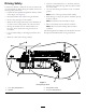
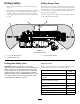
Driving Safety • Check for overhead clearances (i.e. branches, doorways, You drive the machine to and from the work site with the use of a tethered remote. When driving the machine, observe the following safety precautions: • Use care when driving the machine on soft or unstable electrical wires) before driving under any objects and do not contact them. ground. • Operate the drive pendant alongside the machine outside Note: Soft or uneven ground can reduce stability. of the danger zone (Figure 3).
Drilling Safety Drilling Danger Zone • Always lower the pedestrian safety bar before drilling The danger zone is the area within and around the machine where a person is exposed to the risk of injury. This proximity includes where a person is reachable by operational movement of the machine, its working devices, auxiliary equipment, or swinging/falling equipment. (Figure 4). • Ensure that no one approaches a pipe while it is spinning. The pipe can snag on clothing and cause amputation or death.
Electrical Line Safety Water Line Safety If you damage a water line, a potential flood hazard could occur. • Shut off the machine and remove the key. • Remove all individuals from the work area. • Immediately contact the proper emergency and utility authorities to secure the area. WARNING Do not leave the seat of the machine if the machine is charged with electricity.
Noise and Vibration Levels • Keep all parts in good-working condition and all hardware tightened. Replace all worn or damaged decals. WARNING • If any maintenance or repair requires the frame to be in the raised position, secure the frame in the raised position with the hydraulic cylinder lock; refer to Using the Cylinder Lock (page 66). The operator must wear hearing protection when operating the machine. Failure to wear hearing protection may cause hearing loss. • Keep nuts and bolts tight.
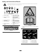
Safety and Instructional Decals Safety decals and instructions are easily visible to the operator and are located near any area of potential danger. Replace any decal that is damaged or lost. Battery Symbols Some or all of these symbols are on your battery 1. Explosion hazard 6. Keep bystanders a safe distance from the battery. 2. No fire, open flame, or smoking. 7. Wear eye protection; explosive gases can cause blindness and other injuries 3. Caustic liquid/chemical burn hazard 4.
125-6137 125-6694 1. Tie-down point 125-8473 125-6108 1. Thrown object hazard—read the Operator’s Manual. 10 1. Explosion hazard—wear eye protection. 3. Fire hazard—keep open flames away. 2. Caustic liquid/chemical burn hazard—rinse affected area and seek medical assistance. 4. Poison hazard—do not tamper with the battery.
125-6114 125-6126 1. Stored energy hazard—do not use tools; read the Operator’s Manual. 1. Entanglement hazard—keep away from moving parts. 125-6119 1. Entanglement hazard—keep away from moving objects. 125-6131 1. Warning—stay at least 3 m (10 ft) away from the machine.
5-6128 125-6115 1. High pressure fluid hazard, injection into the body—read the Operator’s Manual before performing maintenance. 1. Crushing hazard—deploy cylinder locks before performing maintenance. 125-6110 1. Crushing hazard—do not stand under any part of the machine. 125-6130 1. Warning—read the Operator’s Manual; stay at least 3 m (10 ft) away from the front and rear of the machine and 1.8 m (6 ft) away from the sides of the machine.
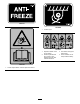
125-6123 1. Load pipes from back row first. 125-6109 1. Electrical shock hazard—when the Zap-Alert system is activated by a power strike, do not leave the operator’s position or touch the ground and the machine at the same time; the machine will be energized with electrical power. 125-6124 1. Center the pipe joint between the upper (makeup/breakout wrench) and lower wrenches (stationary wrench). 125-6111 1. Stake up 6. Stake up 2. Stake down 7. Stake spin counterclockwise 8. Stake down 3.
125-6140 1. Rotate the chair. 125-6107 1. Crushing hazard of hand and foot—keep hands and feet away. 125-6152 1. Move seat forwards and backwards. 125-6116 1. Falling hazard—do not move the machine when someone is in the operator’s position.
125-6158 Model with Cab only 1. Engine—start 13. With trigger released, rock forward to rotate basket toward pipe cam, rock backward to rotate basket toward drill frame. 2. Press down to stop the engine 14. With trigger released, upper button closes pipe gripper, lower button opens pipe gripper. 3. Pull up to start the engine 15.
125-6142 1. Exit-side lockout—reset light 14. Work lights—Off 2. Exit-side lockout—drill-enabled light 15. Press and hold to increase engine speed. 3. Transmitter-battery-status light 16. Engine speed 4. Engine—start 17. Press and hold to decrease engine speed. 5. Press down to stop the engine; pull up to start the engine. 18. Mode I—left trigger released, extends pipe gripper toward drill frame; left trigger pressed, opens lower wrench (stationary wrench). Mode II—spin drill spindle clockwise. 6.
125-1641 1. Forward left 6. Forward right 2. Increase rpm 7. High 3. Engine speed 8. Track speed 4. Decrease rpm 9. Low 10. Reverse right 5. Reverse left 125-6125 1. Warning—read the Operator’s Manual. 2. Explosion hazard; electrical shock hazard—do not dig before calling local services. 3. Press to apply thread-joint compound. 4. Press and hold for maximum drilling fluid pressure; release to stop the flow. 5. Press to turn the drilling-fluid pump on or off. 6.
125-6127 1. Cutting/dismemberment hazard, fan—keep away from moving parts. 0000 0000 0000 125-6129 1. Hot surface—keep away from hot surfaces. 125-6157 125-6141 1. Engine—heating light 4. Engine—start 2. Engine—stop 5. Drill-pendant receptacle 3. Engine—run 6. Drive-pendant receptacle 18 1. Disconnect the battery power. 3. On/Start 2. Off/Stop 4. Read the Operator’s Manual.
125-6113 1. Warning—read the Operator’s Manual. 4. Warning—keep away from moving parts; keep all guards and shields in place. 2. Warning—do not operate the machine unless you are trained. 5. Warning—wear hearing protection. 3. Warning—keep bystanders away from the machine. 6. Explosion hazard, electrical shock hazard; do not dig before calling local utilities. 125-6139 1. Lift point and tie-down point 125-6117 1. Falling hazard—do not stand on the machine while it is moving.
125-1623 1. Forward left track/forward rotary 11. Wrench makeup (for upper wrench) 2. Reverse left track/reverse rotary 12. Raise pipe elevator 3. Drilling fluid pump on 13. Lower pipe elevator 4. Forward right track/forward carriage 14. Reverse cam rotation 5. Reverse right track/reverse carriage 15. Forward (toward operator) cam rotation 6. Tighten lower wrench (stationary wrench) 16. Tighten pipe grip 7. Loosen lower wrench (stationary wrench) 17. Loosen pipe grip 8.
Product Overview Figure 5 1. Drill carriage 6. Front hood 2. Zap-alert strobe 7. Right stabilizer 3. Cab 4. Monitor 5. Track 8. Rear-access door 9. Rear hood 10.
Figure 6 1. Stake-down cage 5. Rear-control panel 2. Pipe holder 6. Left stabilizer 3. Pedestrian safety bar 7. Stake-down plate 4.
Figure 7 1. Cab 5. Upper wrench (makeup/breakout wrench) 2. Thrust frame 6. Lower wrench (stationary wrench) 3. Drill carriage 7. Pipe wiper 4.
Controls Operator-Controls Covers Refer to the following sections for the appropriate machine controls: The covers protect the operator controls from adverse weather conditions, such as rain, wind, sunlight, etc. Remove them before using the machine and replace them before leaving the machine for the day. Each cover is secured with 2 screws as shown in Figure 9. • The Software Guide for this machine.
Exit-Side Lockout—Drill-enabled Light To release the platform and swing it out or in, press up on the front platform latch (Figure 11). This light (Figure 12) illuminates green when the exit-side-lockout feature has been turned off and reset and the machine is ready to drill. Exit-Side Lockout—Reset Switch Press this switch (Figure 12) to enable drilling operation when the reset light illuminates.
Left Joystick—Mode I Front Button Note: The joystick controls vary depending on the control mode you select when powering up the machine. There are 2 control modes: Mode I and Mode II; refer to the Control-Select Screen in the Software Guide for this machine for information on setting the control mode. • Left trigger pressed—press this button to resume the 1 previously set auto-drill speed. Press and hold this button to increase the auto-drill speed.
Left Joystick—Mode II Front Button Note: The joystick controls vary depending on the control mode you select when powering up the machine. There are 2 control modes: Mode I and Mode II; refer to the Control-Select Screen in the Software Guide for this machine for information on setting the control mode. • Left trigger pressed—press this button to resume the 1 previously set auto-drill speed. Press and hold this button to increase the auto-drill speed.
Right Joystick—Mode I Lower Button Note: The joystick controls vary depending on the control mode you select when powering up the machine. There are 2 control modes: Mode I and Mode II; refer to the Control-Select Screen in the Software Guide for this machine for information on setting the control mode. Press this button to turn the drilling-fluid pump on or off. 1 Trigger Press and hold the trigger to move the drill carriage at high speed up or down the drill frame.
Right Joystick—Mode II Lower Button Note: The joystick controls vary depending on the control mode you select when powering up the machine. There are 2 control modes: Mode I and Mode II; refer to the Control-Select Screen in the Software Guide for this machine for information on setting the control mode. Press this button to turn the drilling-fluid pump on or off. 1 Trigger Press and hold the trigger to move the drill carriage at high speed up or down the drill frame.
Exit-Side-Lockout System 1 2 The exit-side-lockout system provides the individuals working around the machine with a means to disable the drill pipe from rotating and thrusting. For more information and instructions, refer to the Operator’s Manual for the Exit-side-lockout system. 3 Rear Control Panel 2 1 3 G0221 15 Figure 18 1. Engine-off position 3. Engine-start position 2. Engine-run position • Engine-off position—turn the key to this position to stop the engine.
Drive Pendant Drill Frame and Stabilizer Controls Refer to Figure 17 for the location of the drive pendant. 1 3 2 4 5 Figure 19 1. Drill-frame tilt lever 3. Right-stabilizer lever 2. Left-stabilizer lever g021855 Figure 20 Stabilizer Levers Use the stabilizer levers to raise and lower the stabilizers. 1. Engine-speed switch 4. Drive-speed switch 2. Drive-direction joystick 5. Operator-presence switch 3.
Drive-Speed Switch The switch sets the speed at which the machine will travel. Move the switch up for high speed or down for low speed. Operator-Presence Switch Press and hold this button to enable the other controls on the drive pendant. The machine will stop moving if you release this button. Drill Pendant WARNING Only an authorized person(s) should operate the drill pendant. Personal injury, harm to others, or damage to the machine could occur if this pendant is misused.
Drilling Fluid and Wrench-Control Switch Pipe-Grip-Control Switch When this switch is connected to the front drill-pendant receptacle, move it to control the drilling-fluid flow or the wrench operation. When this switch is connected to the front drill-pendant receptacle, move it to control the pipe grip. • Move the switch forward to tighten the grip on the pipe. • Move the switch to the left to turn the drilling fluid to • Move the switch backward to loosen the grip on the pipe. the ON position.
Battery-Disconnect Switch Stake-Down Levers Open the rear compartment to access the BATTERY -DISCONNECT switch. Turn the BATTERY -DISCONNECT switch to the ON or OFF position to perform the following: • To energize the machine electrically, rotate the BATTERY -DISCONNECT switch clockwise to the ON position (Figure 23). • To de-energize the machine electrically, rotate the BATTERY -DISCONNECT switch counterclockwise to the OFF position (Figure 23). 1 2 3 4 g021835 Figure 22 1.
Operation 4. Drill the bore. You drill the bore in 3 stages: Note: Determine the left and right sides of the machine from the normal operating position. A. Entry In the entry phase of the bore, you push the drill bit and head into the ground at an angle of up to 16 degrees. After pushing in one or more pipes, you begin drilling down and forward until you reach the desired depth or depth-gauge hole (if used).
Gathering Site Information DANGER Contacting underground hazards with the machine while drilling or reaming can cause explosion, electrocution, breathing problems, severe trauma, and death to you or bystanders.
– Electrical power lines – Crystalline silica and other dust If you will be drilling through or cutting concrete, sand, or other substances that create dusts or fumes, you need to ensure that you and all workers wear breathing protection to protect your lungs from the dust. DANGER Drilling into an electric power line will cause the machine to become electrified and may electrocute you or any bystanders. ◊ Keep bystanders and spectators away from the job site, including the complete bore path.
Planning the Bore Path Before setting up the job site, you need to plan the bore path, including the following: Figure 24 1. Bore entry 4. Obstacle 2. Beginning-of-bore-at-depth point 5. End-of-bore-at-depth point and bore exit 3. Bore depth • Bore entry needed for steering the drill to the surface, typically 9 to 15 m (30 to 50 ft) from the end-of-the-bore-at-depth point. This is where you setup the machine and the drill bit enters the ground.
1 g021765 Figure 25 1. 20 cm (8 inches) This flexibility is often rated in materials as a minimum bend radius, which is the radius of the circle formed if the material or pipes, connected together, were bent to form a giant circle. The minimum radius of a circle made with the pipe used with this machine is 33 m (108.2 ft). 1 2 • Entry pitch g021767 The entry pitch is the angle at which the machine enters the ground.
Note: The depths given in the following table are for 3 m (10 ft) of combined drill head and pipe. As you steer up, the pitch of the steered section will change and can be monitored with the receiver. Use the following table to identify how many lengths of pipe will be necessary to insert and steer to the beginning point and help you choose an entry point.
Given the above information, you can calculate the number of rods required to reach your beginning point at the appropriate depth. Toro recommends that you start the entry point the same distance back from your beginning-at-depth point as the length of pipes you will need to reach that point. This will ensure that you have enough extra space so you will not need to over-steer and damage the pipes.
• Insert the first 3 m (10 ft) of drill bit/pipe into the ground The following example illustrates the process given an installation using the machine at an 18% pitch on level ground: with no steering. The end of the drill bit will be 53 cm (21 inches) deep (Figure 29). Figure 29 1. 18% pitch 3. 96 cm (38 inches) 5. 119 cm (47 inches) 2. 53 cm (21 inches) 4. 114 cm (45 inches) 6. 10.
Testing the Zap-Alert System Preparing the Job Site and the Machine The Zap-Alert system is an electric strike sensing device on the machine that triggers a strobe light and audible alarm in the event that the drill bit, reamer, or stake breaks into an energized power line. In the event of an electric strike, the machine will become energized, setting off the alarm.
7. Disconnect the alligator clips from the grounding stud and the machine. 8. Store the grounding stake in the holder on the operator platform as shown in Figure 31. 1 g021838 Figure 31 Figure 30 1. Test button 2. Zap-alert tester 5. Reset button 6. Alligator clips 3. Zap-alert system 7. Machine grounding point 1. Grounding stake If either the audible alarm or the strobe light fail to trigger when you pressed the TEST button, have them repaired before drilling with the machine. 4.
Loading Drill Pipes into the Pipe Holder Before using the machine, fill the pipe holder with up to 40 drill pipes. Figure 33 1. Pipe 2. Male end 3. Clevis pins Adding Fuel 1. Remove the clevis pins from the pipe holder (Figure 33). Service Interval: Before each use or daily—Check the fuel level. 2. Insert the pipes from the top with the male threaded pipe ends toward the front of the machine (Figure 33). Use only clean, fresh diesel fuel or biodiesel fuels with ultra low (<15 ppm) sulfur content.
Using summer grade fuel above -7° C (20° F) will contribute toward longer fuel pump life and increased power compared to winter grade fuel. DANGER In certain conditions, fuel is extremely flammable and highly explosive. A fire or explosion from fuel can burn you and others and can damage property. Important: Do not use kerosene or gasoline instead of diesel fuel. Failure to observe this caution will damage the engine. • Fill the fuel tank outdoors, in an open area, when the engine is cold.
Checking the Engine-Oil Level Note: Be sure to keep this safe distance whenever moving the machine. Before you start the engine and use the machine, check the oil level in the engine crankcase; refer to Checking the Engine-Oil Level (page 72). 6. Press and hold the OPERATOR PRESENCE button on the drive pendant. Checking the Cooling System 7. Use the SPEED switch on the pendant to increase or decrease the engine speed as desired. 8. Set the desired travel speed using the SPEED switch.
11. Remove the block from the trailer tires, and stow them with the machine for use when unloading it. 12. After driving a few miles, pull over and check to ensure that all chains are still tight and that the machine has not moved. Note: To unload the machine, reverse the above procedure. Setting up the Machine for Drilling 1.
DANGER If the Zap-alert system activates while drilling, the machine, except for the operator platform, will become energized. If you step off the operator platform or if someone touches the machine or wet ground near the machine or in the bore, you or the one who touched the machine could be electrocuted, causing serious injury or death. • Test the Zap-alert system before drilling. Figure 38 • Deploy the grounding stake before drilling. Ensure that the stake is fully inserted into moist soil. 1.
Note: If the ground is soft, place timber below the stabilizers, and lower the stabilizers. 3. If the ground is dry where you put the stake, soak the ground with water before using the machine to ensure good electrical contact. Lowering the Stakes 1. Move the operator station to the desired angle, switch the DRILL/DRIVE switch to the DRILL position, and raise the pipe elevators, so that the pipe is resting on the elevators; refer to Starting the First Pipe (page 51).
• Loosens the soil into which the drill is cutting • Penetrates and binds loose soil to keep it from collapsing 1. Remove the pump-inlet cap (Figure 46). on the bore pipe. Important: Do not operate the drilling-fluid pump without a pressurized supply of drilling fluid, or damage to the pumping system will result. The specific mixture you need will vary depending on your soil type and the operation that you are performing. Refer to your mixing system Operator’s Manual for details.
11. Continue to rotate the drill spindle clockwise, until the male pipe thread is fully seated into the sonde housing or lead bar. 12. Release and retract the pipe-gripper cam to the HOME position. Important: Ensure that you fully retract the pipe gripper and rotate it all the way out or the carriage may collide with the gripper, damaging the machine. 13. Raise the pipe elevator. 14. Retract the cam to the HOME position (past the fourth row of pipes). Figure 47 1. Drill spindle 2.
Setting up the Drill Head and the Tracking System The drill head consists of 2 parts, the drill bit and the sonde housing (Figure 49). Figure 49 1. Sonde housing Figure 50 2. Drill bit Drill bits vary in size and type to meet the various soil conditions that you may need to drill through. Some of the possibilities are as follows: 1. Sonde housing 4. Cover holes 2. Bolts 3. Drill bit 5. Cover 3. Insert the sonde beacon with the forward end toward the drill bit into the sonde housing (Figure 51).
Installing the Drill Head 5. Using the lower wrench (stationary wrench), clamp the lead bar, and tighten the drill spindle to full-seat threads. 1. Using the exit-side-lockout transmitter, activate the exit-side lockout to disable the thrust and rotation of the carriage. 6. Double check the drill head and bit to ensure that the fluid ports are clean and free from obstructions. 7.
Steering the Drill Head 5. Spray the spindle with thread joint compound, then return the drive carriage to the upper end of the frame. The drill bit is shaped like a wedge, angled from one side of the bit to the other. When you push the bit through the soil without rotating it, it will veer toward the direction the wedge is pointing. When you rotate the pipe and drill head, it bores through the soil in a straight path. 6. Rotate the pipe-gripper cam to the closest row of pipes in the pipe holder. 7.
Backreaming and Pullback Note: This may loosen the obstruction and allow you to push past it. After drilling the initial bore, you attach a reamer to the pipe, which is then connected to a the product that you are installing. The reamer is designed to widen the bore, pack the walls, and lubricate the passage of the product into the bore. 2.
Removing Drill Pipes 12. Rotate the drill spindle counterclockwise, moving rearward slowly until the pipes are separated. 1. Using the exit-side-lockout transmitter, enable the exit side lockout. 13. Move the drill carriage back until the male, pipe threads just clear the female end of the lower pipe, then close the upper wrench (makeup/breakout wrench) onto the pipe end, but not on the threads. 2. Install a drill-pipe wiper around the pipe and into the retaining bracket on the front of the machine.
5. Remove and store the last pipe; refer to Removing Drill Pipes (page 57). Using the TJC Applicator 6. Leave the lead bar clamped in the lower wrench (stationary wrench), but do not connect the drill spindle to the lead bar. Adjusting the Applicator Nozzle You can adjust the applicator nozzle to spray thread-joint compound (TJC) either in a fan-shaped spray or as a stream. 7. Remove the reamer from the end of the lead bar as directed by the reamer manufacturer.
Adjusting the TJC-Spray Volume Filling the TJC Applicator 1. Loosen the jam nut on the adjustment bolt located on top of the TJC-applicator piston (Figure 56). 1. Stop the machine and stop the engine. 2. Open the stake-down-guard door. 3. Loosen the wing nuts securing the cover straps to the machine (Figure 57). Figure 56 1. Adjustment bolt 3. TJC-applicator piston 2. Jam nut Figure 57 2. Adjust the bolts as follows: • To increase the applied volume of compound, thread the bolt out (up). 1.
Moving a Disabled Machine Replacing the Pipe Holder 1. Ensure that the 2 upper pins and the 2 lower pins are installed to secure the pipe inside the pipe holder (Figure 59). Whenever the machine is stopped and the engine is not running, the hydrostatic brakes automatically engage. Do not attempt to tow the machine if it cannot move under its own power. If possible, repair the machine at the site.
Positioning the Cab (Model with Cab only) Opening the Door (Model with Cab only) Open the door from the outside by pulling on the handle, and swing the door to the left (Figure 62). Positioning the Cab for Drilling Operation 1. Push back on the SWING-ROCKER switch (until the cab stops) to swing the cab to the DRILL position (Figure 61). Figure 61 1. Swing rocker switch 2. Rotate rocker switch Figure 62 1.
Operating the Air Conditioning Operating the Windshield Wipers (Model with Cab only) and Heating (Model with Cab only) Changing the Windshield-Wiper Speed Air Conditioning the Cab Turn the WINDSHIELD-WIPER knob (Figure 65) to the right increase the speed of the windshield wipers, or turn the knob to the left to decrease the speed. 1. Push the AIR-CONDITIONING switch to the right to turn the air conditioning to the ON position (Figure 64). Figure 65 1.
Maintenance Note: Determine the left and right sides of the machine from the normal operating position. Recommended Maintenance Schedule(s) Maintenance Service Interval Maintenance Procedure After the first 100 hours • Check the stakedown planetary-drive oil level (Also, check if external leakage is observed). • Check the rotary motor planetary-drive oil level (Also, check if external leakage is observed). • Check the thrust motor planetary-drive oil. • Check the gearbox drive oil.
Maintenance Service Interval Maintenance Procedure Every 1,000 hours • Drain and clean the fuel tank. • Check the concentration of the coolant before the winter season. • Clean the cooling system. (Clean the cooling system if the coolant becomes dirty or rust colored.) • Check the tension on the engine drive belt. • Change the hydraulic fluid.
Premaintenance Procedures Opening the Front Hood 1. Park the machine on a level surface, stop the engine, and remove the ignition key. 2. Lift up on the latch as shown in Figure 66. Note: Ensure that the key is in the OPEN (horizontal) position as shown in Figure 66. Figure 68 1. Hood handle Opening the Rear-Access Door 1. Park the machine on a level surface, stop the engine, and remove the ignition key. 2.
Removing and Storing the Cylinder Lock Using the Cylinder Lock WARNING 1. Start the engine. The thrust frame may lower when it is in the raised position, causing serious injury or death. 2. Lower the thrust frame to the fully lowered position. 3. Stop the engine. Install the cylinder lock before performing maintenance that requires the thrust frame to be raised. 4. Remove the cotter pin and the clevis pin that secure the cylinder lock (Figure 70). 5. Remove the cylinder lock. 6.
Lubrication Greasing the Machine Service Interval: Before each use or daily (Grease immediately after every washing). Grease type: General-purpose grease. 1. Park the machine on a level surface, stop the engine, and remove the ignition key. 2. Clean the grease fittings with a rag. 3. Connect a grease gun to each fitting. Figure 74 Front elevator assembly (top view) 4. Pump grease into the fittings until grease begins to ooze out of the bearings (approximately 3 pumps). 5. Wipe up any excess grease.
Figure 77 Rear pipe-loader cam area (6 fittings) Figure 80 Carriage-roller bearings (operator’s side shown; repeat on other side) Figure 78 Hydraulic cylinder and wrench assembly Figure 81 Gearbox float (operator’s side shown; repeat on other side) Figure 82 Stakedown shaft (left side shown; repeat on right side) Figure 79 Stabilizer cylinder and foot (repeat on other side) 68
Engine Maintenance it is necessary only increases the chance of dirt entering the engine when the filter is removed. • Be sure that the cover is seated correctly and seals with Cleaning the Crankcase-Vent Tube the air-cleaner body. Checking the Air-Cleaner Indicator Service Interval: Before each use or daily—Check the crankcase-vent tube and clean it if necessary. Service Interval: Before each use or daily 1. Start the engine. 1.
Cleaning the Dust Valve Service Interval: Every 50 hours 1. Park the machine on a level surface, stop the engine, and remove the ignition key. 2. Open the rear-access door; refer to Opening the Rear-Access Door (page 65). 3. Squeeze the sides of the dust valve on the air-cleaner cover to release any collected water, dust, or dirt from the valve. (Figure 84). Note: Ensure that there are no obstructions inside the dust valve. Figure 85 1. Air-cleaner cover latches 6.
Servicing the Engine Oil and Filter 4. Using the air-filter handles, remove the primary filter from the air-cleaner cover (Figure 86). Important: Do not clean the used filter. The engine is shipped with oil in the crankcase; however, check the oil level before and after you first start the engine. Crankcase capacity: 7.5 L (7.9 US qt) with the filter. Use only high-quality low ash SAE 15W-40 heavy-duty engine oil with an API classification of CJ-4 (ACEA E9) or higher.
Checking the Engine-Oil Level B. Service Interval: Before each use or daily—Check the engine oil level. Install the oil-fill cap and the dipstick. Changing the Engine-Oil Filter 1. Park the machine on a level surface, stop the engine, and remove the ignition key. Service Interval: Every 250 hours 2. Open the front hood. 1. Park the machine on a level surface, stop the engine, and remove the ignition key. 3. Remove the dipstick (Figure 88), and wipe it clean. 2. Open the front hood. 3.
Changing the Engine Oil Service Interval: Every 250 hours 1. Park the machine on a level surface, stop the engine, and remove the ignition key. WARNING Allow the engine and oil to cool before draining the oil. Hot oil may cause serious injury. Figure 92 2. Ensure that the drain hose (Figure 91) is carefully pulled up and the end of the hose is placed in a drain pan. 1. Filler neck 2. Oil-fill cap 3. Funnel Note: Use a funnel with a flexible, attached hose to direct the engine oil into the engine. 9.
Fuel System Maintenance Note: If the fuel-water separator has any water or sediment, also drain the water and sediment from the fuel tank; refer to Draining Water from the Fuel Tank (page 74). 5. When clean fuel appears, rotate the drain valve clockwise until it is closed. DANGER Under certain conditions, diesel fuel and fuel vapors are highly flammable and explosive. A fire or explosion from fuel can burn you and others and can cause property damage.
Priming the Fuel System WARNING The fuel system is under high pressure. Bleeding the system without proper precautions and training could result in injury to you from injected fluid or fire or explosion. Note: Prime the fuel system whenever any of the following occurs: • You drained water from the fuel filter. • You replaced the fuel filter. Read the engine owner’s manual for the proper bleeding procedure or contact your Authorized Toro Dealer.
Replacing the Secondary Fuel Filter Draining and Cleaning the Fuel Tank 1. Park the machine on a level surface, stop the engine, and remove the ignition key. Service Interval: Every 1,000 hours/Yearly (whichever comes first)—Drain and clean the fuel tank. 2. Open the front hood; refer to Opening the Front Hood (page 65). 3. Align a drain pan or several rags under the secondary fuel filter and the fuel-filter adapter (Figure 96).
Electrical System Maintenance A battery contains sulfuric acid, which can cause serious burns; and it can produce explosive gases. Servicing the Battery • Avoid contact with skin, eyes, or clothing; flush affected areas with water. WARNING Service Interval: Every 50 hours—Check the battery condition. • If taken internally, drink large quantities of water or milk. Do not induce vomiting. Seek medical attention immediately.
Charging the Battery Battery-charger Table WARNING Charging the battery produces gasses that can explode. Charger setting Charging time 4 to 6 amperes 30 minutes 25 to 30 amperes 10 to 15 minutes 8. When the battery is fully charged, unplug the charger from the electrical source, then disconnect the charger leads from the battery posts (Figure 97). Do not smoke near the battery, and keep sparks and flames away from the battery. Important: Keep the battery fully charged.
Drive System Maintenance Checking the Oil Level for the Stakedown Planetary Drive Service Interval: After the first 100 hours—Check the stakedown planetary-drive oil level (Also, check if external leakage is observed). Every 500 hours—Check the stakedown planetary-drive oil level (Also, check if external leakage is observed). Figure 98 1. Ground point (unpainted bolt) 4. Cover Oil specification: SAE 85W-140 API classification level GL4 2. Jumper-cable clamp (negative) 5.
Checking the Oil Level for the Tracks Planetary Drive Changing the Oil for the Tracks Planetary Drive Service Interval: Every 50 hours—Check the tracks rotary motor planetary-drive oil level (Also, check if external leakage is observed). Service Interval: After the first 250 hours—Change the planetary-drive oil. Every 800 hours—Change the planetary-drive oil (or yearly, whichever comes first). Oil specification: SAE 85W-140 API classification level GL4 Note: Change the oil when it is warm, if possible.
Checking the Oil Level for the Rotary Motor Planetary Drive Checking the Oil for the Thrust Motor Planetary Drive Service Interval: After the first 100 hours—Check the rotary motor planetary-drive oil level (Also, check if external leakage is observed). Service Interval: After the first 100 hours—Check the thrust motor planetary-drive oil. Every 500 hours—Check the thrust motor planetary-drive oil (or yearly, whichever comes first).
Checking the Oil for the Gearbox Drive Changing the Oil for the Gearbox Drive Service Interval: After the first 100 hours—Check the gearbox drive oil. Service Interval: After the first 100 hours—Change the gearbox-drive oil. Every 500 hours—Check the gearbox drive oil (or yearly, whichever comes first). Every 500 hours—Change the gearbox-drive oil (or yearly, whichever comes first). Note: Change the oil when it is warm, if possible. Oil specification: SAE 85W-140 API classification level GL4 1.
Servicing the Tracks 3. Remove the 2 bolts and nuts on the carriage guard (Box B of Figure 104). Service Interval: Before each use or daily—Check the track tension. 4. Remove the 2 bolts and nuts on the side of the carriage guard (Box C of Figure 104). WARNING 5. Slide the carriage guard forward (Box D of Figure 104). 6. Remove the 6 bolts on the gearbox (Box E of Figure 104).
Cooling System Maintenance 1. Park the machine on a level surface, stop the engine, and remove the ignition key. 2. Remove dirt and debris found around the track-tension grease valve (Figure 106). Coolant specification: 50/50 solution of ethylene-glycol antifreeze and water or equivalent Important: Ensure that the entire area surrounding the track-tension grease valve is clean before beginning to adjust the track tension. Engine and Radiator coolant capacity: 16.8 L (17.7 US qt) 3.
Checking the Coolant Level in the Radiator Checking the Condition of Cooling-System Components Service Interval: Before each use or daily Service Interval: Every 300 hours/Yearly (whichever comes first) WARNING Check the condition of the cooling system for leaks, damage, dirt, and loose hoses and clamps. Clean, repair, tighten, and replace the components as necessary. If the engine has been running, the radiator will be pressurized and the coolant inside will be hot.
Draining the Coolant from the System Flushing the Cooling System Important: Do not pour coolant onto the ground or into an unapproved container that can leak. Engine and radiator coolant capacity: 16.8 L (17.7 US qt) 1. Park the machine on a level surface, stop the engine, and remove the ignition key. 1. Park the machine on a level surface, stop the engine, and remove the ignition key. 2. Condition the cooling system as follows: 2. Allow the engine to cool. A.
A. Open the filler-neck cap. Filling the System with Coolant B. Important: You must fill the cooling system properly to prevent air locks in the cooling passages. Failing to vent the cooling system properly can severely damage the cooling system and engine. Fill the radiator with clean water (Figure 110). Important: Use a mixture of 50% ethylene glycol and 50% water mixture or equivalent in the machine. The lowest ambient operating temperature for this mixture is above -37° C (-34° F).
Belt Maintenance 3 Servicing the Engine-Drive Belt 2 1 WARNING Contacting a rotating belt can cause serious injury or death. Stop the engine and remove the ignition key before working near belts. G022028 Figure 113 1. Coolant level (at the bottom of the filler neck) Checking the Condition of the Belt 3. Coolant (50/50 ethylene glycol and water or equivalent) Service Interval: Every 250 hours 1. Park the machine on a level surface, stop the engine, and remove the ignition key. 2. Filler neck 2.
Adjusting the Tension of the Belt Checking the Tension of the Belt 1. Park the machine on a level surface, stop the engine, and remove the ignition key. Service Interval: Every 1,000 hours 1. Park the machine on a level surface, stop the engine, and remove the ignition key. 2. Open the front hood. 2. Open the front hood. 3. Loosen the nut and bolt at the pivot point for the alternator (Figure 115). 3. Align a straight edge over the drive belt and across the pulleys as shown in Figure 114.
Checking the Hydraulic Fluid Hydraulic System Maintenance Service Interval: Before each use or daily Check the hydraulic fluid as follows: Servicing the Hydraulic Fluid 1. Park the machine on a level surface, stop the engine, and remove the ignition key. The hydraulic reservoir is filled at the factory with approximately 170 L (45 US gallons) of high-quality hydraulic fluid. Check the level of the hydraulic fluid before the engine is first started and daily thereafter.
Changing the Hydraulic Fluid Note: Do not overfill. Service Interval: Every 1,000 hours/Yearly (whichever comes first) Changing the Hydrostatic-Charge Filter Important: If the fluid becomes contaminated, contact your Authorized Toro Dealer, because the system must be flushed. Contaminated fluid looks milky or black when compared to clean oil. Service Interval: Every 500 hours/Every 6 months (whichever comes first) 1. Park the machine on a level surface, stop the engine, and remove the ignition key.
Changing the High-Pressure Hydraulic Filter Changing the Hydraulic-Return Filter Service Interval: Every 1,000 hours Service Interval: Every 1,000 hours 1. Park the machine on a level surface, stop the engine, and remove the ignition key. WARNING 2. Open the rear-access door. Ensure that the engine is in the OFF position before removing the high-pressure hydraulic filter.
Drilling-Fluid Pump Maintenance Checking the Hydraulic Lines and Hoses Service Interval: Every 2 years—Replace moving hoses. Inspect the hydraulic lines and hoses daily for leaks, kinked lines, loose mounting supports, wear, loose fittings, weather deterioration, and chemical deterioration. Make all necessary repairs before operating. Servicing the Drilling-Fluid-Pump Oil The drilling-fluid pump is shipped with oil in the crankcase; however, check the oil level before and after you first start the engine.
Checking the Drilling-Fluid-Pump Oil Level Changing the Drilling-Fluid-Pump Oil Service Interval: Every 500 hours—Change the drilling-fluid pump oil. Service Interval: Before each use or daily—Check the drilling-fluid pump oil level. 1. Park the machine on a level surface, stop the engine, and remove the ignition key. 1. Park the machine on a level surface, stop the engine, and remove the ignition key. 2. Allow the engine to cool. 2. Remove the oil-level plug on the crankcase (Figure 121). 3.
Preparing the Drilling-Fluid System for Cold Weather Changing the Drilling-Fluid-Pump, Charge Filter 1. Park the machine on a level surface, stop the engine, and remove the ignition key. Prepare the machine as follows after drilling if the temperature will be below 0° C (32° F). 2. Open the front hood. 1. Park the machine on a level surface, stop the engine, and remove the ignition key. 3. Align a drain pan or several rags under the charge filter (Figure 123). 2.
Figure 128 1. Valve (open position) Figure 126 1. Antifreeze-tank cap D. 2. Antifreeze tank Ensure that the tank is full of antifreeze (Figure 126). C. Start the machine and turn On the drilling-fluid pump. D. Add antifreeze to the tank as needed (Figure 126). E. When the antifreeze comes out of the drill spindle (Figure 124), turn the pump off. 3. Circulate the antifreeze as follows: A. Open the antifreeze valve inside of the rear compartment (Figure 127). 4. Turn the machine off. 5.
Cab Maintenance Changing the Cab Air Filter 1. Open the cab door; refer to Opening the Door (Model with Cab only) (page 61). 2. Park the machine on a level surface, stop the engine, and remove the ignition key. 3. Remove the screw and the cover that house the air filter (Figure 129). Figure 130 1. Air filter 2. Air-filter cover 3. Screw Filling the Windshield-Washer Fluid Tank 1. Open the cab door; refer to Opening the Door (Model with Cab only) (page 61). 2.
Cleaning Cleaning with the Spray-Hose Attachment Service Interval: Before each use or daily The machine comes with a spray-hose attachment that you can use to clean the machine and pipes. Important: Do not spray any electronic component of the machine and ensure that the hood is down before cleaning the machine with the spray-hose attachment. Figure 133 1.
Storage 1. Stop the engine and remove the key. 2. Remove dirt and grime from the entire machine; refer to Cleaning with the Spray-Hose Attachment (page 98). 3. Service the air cleaner; refer to Servicing the Air-Cleaning System (page 69). 4. Grease the machine; refer to Greasing the Machine (page 67). 5. Charge the battery; refer to Charging the Battery (page 78). 6. Check and adjust the track tension; refer to Servicing the Tracks (page 83). 7.
Troubleshooting Problem The starter does not crank. The engine cranks, but does not start. Possible Cause Corrective Action 1. The BATTERY -DISCONNECT switch is in the OFF position. 1. Turn the BATTERY -DISCONNECT switch to the ON position. 2. The electrical connections are corroded or loose. 3. A fuse is blown or loose. 4. The battery is discharged. 5. The relay or switch is damaged. 6. A starter or starter solenoid is damaged. 7. The internal engine components have seized. 2.
Problem The engine starts, but does not keep running. Possible Cause 1. The fuel tank vent is restricted. 1. Loosen the cap. If the engine runs with the cap loosened, replace the cap. 2. Dirt or water is in the fuel system. 2. Drain and flush the fuel system; add fresh fuel. 3. Replace the fuel filter. 4. Bleed the nozzles and check for air leaks at fuel hose connections and fittings between the fuel tank and engine. 5. Drain the fuel system and replace the fuel filter.
Problem The engine overheats. Possible Cause 1. More coolant is needed. 1. Check and add coolant. 2. There is restricted air flow to the radiator. 3. The crankcase oil level is incorrect. 4. There is excessive loading. 2. Inspect and clean the side panel screens with every use. 3. Fill or drain to the full mark. 4. Reduce the load and use a lower ground speed. 5. Drain and flush the fuel system; add fresh fuel. 6. Contact your Authorized Service Dealer. 7. Contact your Authorized Service Dealer. 8.
Index 811 ............................. 4, 35–36 A Accessories. . . . . . . . . . . . . . . . . . . . . . . . . . . . . . . . 34 Adding drill pipes . . . . . . . . . . . . . . . . . . . . . . . . . . 54 Adding fuel. . . . . . . . . . . . . . . . . . . . . . . . . . . . . . . . . 45 Air conditioning the cab . . . . . . . . . . . . . . . . . . . 62 Air filter Cab Changing . . . . . . . . . . . . . . . . . . . . . . . . . . . . . 97 Air-cleaning system Checking the air-cleaner indicator. . . . .
Drill-frame tilt lever . . . . . . . . . . . . . . . . . . . . . . . . 31 Drill-pendant receptacle . . . . . . . . . . . . . . 30, 32 Drill-spindle-control switch. . . . . . . . . . . . . . . . 33 Drilling. . . . . . . . . . . . . . . . . . . . . . . . . . . . . . . . . . . . . . 51 Adding drill pipes . . . . . . . . . . . . . . . . . . . . . . . 54 Directional Concept . . . . . . . . . . . . . . . . . . . . . . . . . . . . . . . 43 Entry shaft. . . . . . . . . . . . . . . . . . . . . . . . . . . . . . .
Location . . . . . . . . . . . . . . . . . . . . . . . . . . . . . . . . . 24 Mode I . . . . . . . . . . . . . . . . . . . . . . . . . . . . . . . . . . . 26 Mode II . . . . . . . . . . . . . . . . . . . . . . . . . . . . . . . . . . 27 Left-stabilizer lever . . . . . . . . . . . . . . . . . . . . . . . . 31 Left-track-control switch . . . . . . . . . . . . . . . . . . 32 Length. . . . . . . . . . . . . . . . . . . . . . . . . . . . . . . . . . . . . . 34 Lever Drill-frame tilt . . . . . . . . . . . . . . .
Receiver-battery-status light. . . . . . . . . . . . . . 25 Receptacle Drill-pendant . . . . . . . . . . . . . . . . . . . . . . . . 30, 32 Drive-pendant . . . . . . . . . . . . . . . . . . .30, 32, 47 Removing drill pipes . . . . . . . . . . . . . . . . . . . . . . 58 Removing the last pipe . . . . . . . . . . . . . . . . . . . 57 Removing the reamer . . . . . . . . . . . . . . . . . . . . . 57 Replacing the fuel filters . . . . . . . . . . . . . . . . . . 75 Replacing the pipe holder . . . . . . . . . . .
Wire Connecting to a reamer . . . . . . . . . . . . . . . . 56 Wrench Enable controls . . . . . . . . . . . . . . . . . . . . . 26–27 Lower Close . . . . . . . . . . . . . . . . . . . . . . . . . . . . . . 26, 29 Location. . . . . . . . . . . . . . . . . . . . . . . . . . . . . . . 23 Open . . . . . . . . . . . . . . . . . . . . . . . . . . . . . . 26, 29 Upper Close . . . . . . . . . . . . . . . . . . . . . . . . . . . . . . 26–27 Location. . . . . . . . . . . . . . . . . . . . . . . . . . . . . . .
Notes: 108
Notes: 109
Notes: 110
International Distributor List Distributor: Country: Phone Number: Distributor: Phone Number: 57 1 236 4079 Colombia Japan 81 3 3252 2285 Czech Republic 420 255 704 220 420 255 704 Slovakia 220 Argentina 54 11 4 821 9999 Russia 7 495 411 61 20 Ecuador 593 4 239 6970 Finland 358 987 00733 Agrolanc Kft Balama Prima Engineering Equip. B-Ray Corporation Hungary Hong Kong Korea 36 27 539 640 852 2155 2163 82 32 551 2076 Maquiver S.A. Maruyama Mfg. Co. Inc. Mountfield a.s.
Underground Equipment The Toro Underground Warranty A Limited Warranty Conditions and Products Covered The Toro Company and its affiliate, Toro Warranty Company, pursuant to an agreement between them, jointly warrant your Toro Underground Equipment (“Product”) to be free from defects in materials or workmanship. Where a warrantable condition exists, we will repair the Product at no cost to you including diagnostics, labor, and parts.