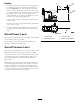
Form No. 3383-875 Rev A Gas-Powered FM 330 Fluid Mixer Model No. 23890—Serial No. 313000001 and Up G023981 Register at www.Toro.com.
Read this information carefully to learn how to operate and maintain your product properly and to avoid injury and product damage. You are responsible for operating the product properly and safely. This product complies with all relevant European directives. For details, please see the separate product-specific Declaration of Conformity (DOC) sheet. WARNING You may contact Toro directly at www.Toro.com for product and accessory information, help finding a dealer, or to register your product.
Safety and Note emphasizes general information worthy of special attention. Improperly using or maintaining the machine can result in injury. To reduce the potential for injury, comply with these safety instructions and always pay attention to the safety alert symbol , which means: Caution, Warning, or Danger—personal safety instruction. Failure to comply with the instruction may result in personal injury or death. Contents Introduction ..................................................................
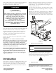
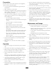
Preparation • Do not touch parts which may be hot from operation. Allow them to cool before attempting to maintain, adjust, or service the machine. Become familiar with the safe operation of the equipment, operator controls, and safety signs. • Never move the machine while the engine is running. • Ensure that all the guards and shields are securely in place • Use only accessories and attachments approved by the manufacturer. before operating the machine. • Wear a respirator or a dust mask.
Hauling 1 2 • Ensure that the transport vehicle has a carrying capacity to handle the weight of the machine and a full tank of fluid—in addition to any other machines or materials that the transport vehicle may need to carry. The mixing system alone requires a carrying capacity of at least 2,268 kg (5,000 lb) for a system that uses a single 1,893 L (500-gallon) tank, up to 9,072 kg (20,000 lb) for a system that uses two 3,785 L (1000-gallon) tanks.
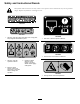
Safety and Instructional Decals Safety decals and instructions are easily visible to the operator and are located near any area of potential danger. Replace any decal that is damaged or lost. 117-2718 119–0217 125–6156 1. Warning—stop the engine; keep away from moving parts; keep all guards and shields in place. 1. Tank drain—read the Operator’s Manual. 125–6161 1. Use E10 fuel; do not use E15 or E85 fuel. 125–6155 1. Warning—read the Operator’s Manual. 3.
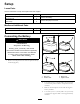
Setup Loose Parts Use the chart below to verify that all parts have been shipped. Description Use Qty. 2 2 1 3 Bolt (5/16 x 3/4 inch) Nut (5/16 inch) Circulation hose Hose clamp Connect the battery. Connect the pump to the tank. Media and Additional Parts Description Use Qty. 1 Transfer hose Connect the mixer to the drill.
Connecting the Pump to the Tank Ensure that the frame of the fluid mixer and the frame of the tank are secured to a strong surface, with an adequate fastener through each mounting hole (Figure 5). G025173 1 Note: Ensure that the mixer and the tank are in a position that allows the hoses to connect them without stretching or kinking. 1 2 3 Figure 7 1. Fitting 3. Hose 2. Hose clamp 1 G024041 1 Figure 8 1. Locknut 2 2 1 1 G024044 3. Tighten the hose clamp by tightening the locknut.
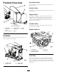
Circulation Valve Product Overview 1 The circulation valve (Figure 10) controls the flow from the pump to the tank. 2 8 Suction Valve 3 7 The suction valve (Figure 10) controls the flow from the tank to the pump. 6 Hopper Valve The hopper valve (Figure 10) controls the flow from the hopper into the mixing system. The hopper valve is most effective when it is just slightly open, as the fluid then creates a vacuum effect and draws the bentonite and other components into the flow.
1 2 3 4 1 2 5 3 G019815 Figure 12 G023982 1. Choke lever 2. Fuel valve 3. Throttle lever Figure 13 1. Start position 4. Ignition switch 2. On position 5. Circuit-protector button 3. Off position Choke Lever Use the choke lever (Figure 12) to start a cold engine. Before pulling the recoil-start handle, move the choke lever to the closed position. Once the engine is running, move the choke lever to the open position.
Specifications Mixer Flow rate Length Up to 1249 L/minute (330 141 cm (55.4 inches) gallons/minute) Width Height Weight 90 cm (35.3 inches) 116 cm (45.8 inches) 209 kg (460 lb) Tanks Capacity Length Width Height Dry weight 1893 L (500 US gallons) 203 cm (80.0 inches) 79 cm (31.0 inches) 177.8 cm (70.0 inches) 241 kg (532 lb) 109 cm (42.8 inches) 191 cm (75.3 inches) 397 kg (876 lb) 3785 L (1000 US gallons) 257 cm (101.
DANGER WARNING In certain conditions, fuel is extremely flammable and highly explosive. A fire or explosion from fuel can burn you and others and can damage property. Fuel is harmful or fatal if swallowed. Long-term exposure to vapors can cause serious injury and illness. • Fill the fuel tank outdoors, in an open area, when the engine is cold. Wipe up any fuel that spills. • Avoid prolonged breathing of vapors. • Keep your face away from the nozzle and the fuel tank or conditioner opening.
1 1 G019799 Figure 15 1. Fuel cap 3. Add unleaded gasoline to the fuel tank, until the level is at the bottom of the maximum fuel level, as shown in Figure 16. G020679 Figure 16 1. Maximum fuel level Important: The extra space in the tank allows gasoline to expand. Do not fill the fuel tank completely full. 4. Install the fuel cap securely (Figure 15). 5. Wipe up any gasoline that may have spilled.
Starting and Stopping the Engine 30 5W - 30 / 10W - 30 0 20 40 -20 -10 0 60 10 80 20 30 WARNING 100 F If you run the engine when the mixing valves are not adjusted as directed, the pump can direct fluid out through the hopper and push the grate into the air. o 40 C o Ensure that the mixing valves are adjusted appropriately and that the grate is tethered to the hopper, before starting the engine. g013375 Figure 17 1. Place the machine on a flat, level surface, and stop the engine.
Stopping the Engine • To start a cold engine, move the choke lever to the Closed position—all the way to the left (Figure 19); refer to Choke Lever (page 10). WARNING • To start a warm engine, move the choke lever in In an emergency situation, stop the engine immediately. the Open position—all the way to the right. 4. Rotate the engine switch to the On position (Figure 19); refer to Electric-start Switch (page 10).
Ensure that there is enough room for additives in the mixing system. 1 4. Test the pH of the water. If it is below 8, add soda ash until the pH is 8 or higher. Note: Supplies for testing pH are available where swimming-pool supplies are sold. 5. Slightly open the valve at the bottom of the hopper. Note: The valve works more effectively when it is open only slightly; it creates a vacuum effect that allows the dry components to enter the mixer at a faster rate. 2 6.
3. Drain the tank; refer to Draining the Tank (page 16). Operating Tips 4. Drain any remaining fluid from the pump by removing the drain plug in the bottom of the pump (Figure 22). • Use the correct fluid formula for the situation and the soil conditions. • When using fluid with any polymer in it, do not over-mix the fluid, as over-mixing can lower the viscosity of it. Partially close the circulation valve, or decrease the engine speed; refer to Throttle Lever (page 10).
Maintenance Important: Before performing any maintenance procedures, first stop the engine, wait 5 minutes to allow all moving parts to come to a complete stop and cool, and disconnect the spark-plug wire. Recommended Maintenance Schedule(s) Maintenance Service Interval Maintenance Procedure After the first 25 hours • Change the engine oil. Before each use or daily • Check the engine-oil level. • Inspect the air-cleaner elements. After each use • Clean the machine.
Premaintenance Procedures Lubrication Preparing the Machine for Maintenance Service Interval: Every 100 hours Lubricating the Pump Grease Type: NLGI #1 heavy-duty EP grease (Toro part 505-162) 1. Park the transport vehicle on a level surface and chock the tires, or remove the machine from the transport vehicle. Use a grease gun to pump grease into the grease fitting on the side of the pump (Figure 24). 2. Ensure that the engine and muffler are cool. 3.
Engine Maintenance 1 Servicing the Air Cleaner 2 Service Interval: Before each use or daily—Inspect the air-cleaner elements. Every 50 hours—Clean the air-cleaner elements. Clean them more frequently in dusty operating conditions. 3 Every 300 hours/Yearly (whichever comes first)—Replace the paper air-cleaner element. Replace it more frequently in dusty operating conditions. 4 Important: Do not operate the engine without the air-filter assembly; extreme engine damage will occur. 1.
Draining the Engine Oil 10. Rinse and dry the foam element thoroughly. 11. Dip the foam element in clean engine oil, then squeeze out the excess oil. WARNING Oil may be hot after the engine has been run, and contact with hot oil can cause severe personal injury. Note: Excess oil in the foam element restricts the air flow through the element and may reach the paper filter and clog it. 12. Wipe dirt from the base and the cover with a moist rag. Avoid contacting the hot engine oil when you drain it.
Filling the Engine Crankcase with Oil 1. Remove the dipstick (Figure 28) and slowly pour oil into the fill hole until the oil reaches the upper-limit mark (bottom edge of the oil-fill hole) on the dipstick. 1 2 3 Figure 29 1. Spark plug 4 2. Wire 4. Clean around the spark plug. 5. Rotate the spark plug counterclockwise using a 13/16 inch (21 mm) spark-plug wrench to remove the plug and the sealing washer (Figure 30). G019746 Figure 28 1. Oil-fill hole 3. Oil-level upper limit 2. Dipstick 4.
1 2 3 Servicing the Spark Arrester 4 Cleaning the Spark Arrester Service Interval: Every 100 hours Note: A spark arrester is available as an option. If you require a spark arrester, contact your Authorized Toro Service Dealer. Genuine Toro spark arresters are approved by the USDA Forestry Service. G019300 Figure 31 1. Side electrode 2. Center electrode WARNING 3. Insulator 4. 0.7 to 0.8 mm (0.028 to 0.031 inch) gap If the engine has been running, the muffler will be hot. 1.
Fuel System Maintenance Servicing the Fuel System 1 G019332 Cleaning the Sediment Cup 2 Figure 33 1. Screen Service Interval: Every 100 hours/Every 6 months (whichever comes first)—Clean the sediment cup. Yearly or before storage—Clean the fuel sediment cup. 2. Brush 6. Install the spark arrester, muffler protector, exhaust deflector, and muffler in the reverse order of disassembly. Underneath the fuel valve is a sediment cup to catch dirt in the fuel. 1.
Electrical System Maintenance 10. Move the lever of the fuel valve to the On position (all the way to the right) and check for leaks. If it leaks, replace the O-ring. Inspecting and Replacing the Fuse The engine has a fuse (Figure 35) that protects the electric-starter relay circuit and the battery-charging circuit. If the fuse burns out, the electric starter will not work. You can still start the engine with the recoil-start handle, but the engine will not charge the battery.
Replacing the Battery Charging the Battery 1. Remove the cover of the battery box. WARNING 2. Disconnect the negative (black) ground cable from the battery post. Charging the battery produces gases that can explode, seriously injuring you or bystanders. WARNING Never smoke near the battery, and keep sparks and flames away from the battery. Incorrect battery cable routing could damage the machine and cables, causing sparks. Sparks can cause the battery gases to explode, resulting in personal injury.
Checking and Cleaning the Battery Cleaning Cleaning the Machine Service Interval: Every 100 hours—Check the battery cable connections. Regular cleaning and washing will increase the life span of the machine. Clean the machine after each use, before the dirt hardens. Keep the top of the battery clean. If the machine is stored in a location where temperatures are extremely high, the battery will discharge more rapidly than if the machine is stored in a cooler location.
Storage Note: Do not install the wire on the spark plug. 10. Grease the machine; refer to Lubricating the Pump (page 19). Storing the Machine 11. Check and tighten all bolts, nuts, and screws. Repair or replace any part that is damaged. For storage over 30 days, prepare the machine as follows: 1. Remove dirt and grime from the external parts of the entire machine, especially the engine. Clean dirt and debris from the outside of the engine cylinder-head fins and the blower housing. 12.
Troubleshooting Problem The engine does not start. Possible Cause 1. The fuel-valve lever is in the Off position. 1. Move the fuel-valve lever to the On position. 2. The choke is closed. 2. Open the choke when starting a hot engine. 3. Close the choke when starting a cold engine. 4. Rotate the switch to the On position. 3. The choke is open. 4. The engine On/Off switch is in the Off position. 5. The engine oil level is low (engines with the oil-level switch). 6. The fuel tank is empty. 7.
Notes: 30
Notes: 31
Underground Equipment The Toro Underground Warranty A Limited Warranty Conditions and Products Covered The Toro Company and its affiliate, Toro Warranty Company, pursuant to an agreement between them, jointly warrant your Toro Underground Equipment (“Product”) to be free from defects in materials or workmanship. Where a warrantable condition exists, we will repair the Product at no cost to you including diagnostics, labor, and parts.