Form No. 3383-981 Rev A Diesel-Powered FM 330 Fluid Mixer Model No. 23892—Serial No. 313000001 and Up G024228 Register at www.Toro.com.
Read this information carefully to learn how to operate and maintain your product properly and to avoid injury and product damage. You are responsible for operating the product properly and safely. This product complies with all relevant European directives. For details, please see the separate product-specific Declaration of Conformity (DOC) sheet. WARNING You may contact Toro directly at www.Toro.com for product and accessory information, help finding a dealer, or to register your product.
Safety and Note emphasizes general information worthy of special attention. Improperly using or maintaining the machine can result in injury. To reduce the potential for injury, comply with these safety instructions and always pay attention to the safety alert symbol , which means: Caution, Warning, or Danger—personal safety instruction. Failure to comply with the instruction may result in personal injury or death. Contents Introduction ..................................................................
Preparation • Do not touch parts which may be hot from operation. Allow them to cool before attempting to maintain, adjust, or service the machine. Become familiar with the safe operation of the equipment, operator controls, and safety signs. • Never move the machine while the engine is running. • Ensure that all the guards and shields are securely in place • Use only accessories and attachments approved by the manufacturer. before operating the machine. • Wear a respirator or a dust mask.
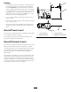
Hauling 1 2 • Ensure that the transport vehicle has a carrying capacity to handle the weight of the machine and a full tank of fluid—in addition to any other machines or materials that the transport vehicle may need to carry. The mixing system alone requires a carrying capacity of at least 2,268 kg (5,000 lb) for a system that uses a single 1,893 L (500-gallon) tank, up to 9,072 kg (20,000 lb) for a system that uses two 3,785 L (1000-gallon) tanks.
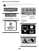
Safety and Instructional Decals Safety decals and instructions are easily visible to the operator and are located near any area of potential danger. Replace any decal that is damaged or lost. 117-2718 125–6155 1. Warning—read the Operator’s Manual. 119–0217 3. Explosion hazard; electrical shock hazard—Call local utilities before digging underground. 1. Warning—stop the engine; keep away from moving parts; keep all guards and shields in place. 2.
125-6177 1. Fast 3. Warning—do not stop the engine at high speeds; only stop the engine at slow speed. 2.
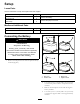
Setup Loose Parts Use the chart below to verify that all parts have been shipped. Description Use Qty. 2 2 1 3 Bolt (5/16 x 3/4 inch) Nut (5/16 inch) Circulation hose Hose clamp Connect the battery. Connect the pump to the tank. Media and Additional Parts Description Use Qty. 1 Transfer hose Connect the mixer to the drill.
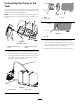
Connecting the Pump to the Tank Ensure that the frame of the fluid mixer and the frame of the tank are secured to a strong surface, with an adequate fastener through each mounting hole (Figure 5). G025173 1 Note: Ensure that the mixer and the tank are in a position that allows the hoses to connect them without stretching or kinking. 1 2 3 Figure 7 1. Fitting 3. Hose 2. Hose clamp 1 G024041 1 Figure 8 1. Locknut 2 2 1 1 G024044 3. Tighten the hose clamp by tightening the locknut.
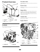
Circulation Valve Product Overview 1 The circulation valve (Figure 10) controls the flow from the pump to the tank. 2 8 Suction Valve 3 7 The suction valve (Figure 10) controls the flow from the tank to the pump. 6 Hopper Valve The hopper valve (Figure 10) controls the flow from the hopper into the mixing system. The hopper valve is most effective when it is just slightly open, as the fluid then creates a vacuum effect and draws the bentonite and other components into the flow.
Electric-start Switch Speed-control Handle The electric-start switch (Figure 12) allows the operator of the machine to start the engine. This switch is located on the front of the engine. Rotate the ignition switch to the Start position to start the engine. Rotate the ignition switch to the Run position to allow the engine to run. After you stop the engine with the speed-control handle, rotate the ignition switch to the Off position.
Specifications Mixer Flow rate Length Up to 1249 L/minute (330 141 cm (55.4 inches) gallons/minute) Width Height Weight 90 cm (35.3 inches) 116.2 cm (45.8 inches) 204 kg (450 lb) Tanks Capacity Length Width Height Dry weight 1893 L (500 US gallons) 203.2 cm (80.0 inches) 78.7 cm (31.0 inches) 177.8 cm (70.0 inches) 241 kg (532 lb) 108.6 cm (42.8 inches) 191.1 cm (75.3 inches) 397 kg (876 lb) 3785 L (1000 US gallons) 257.2 cm (101.
DANGER WARNING In certain conditions, fuel is extremely flammable and highly explosive. A fire or explosion from fuel can burn you and others and can damage property. Fuel is harmful or fatal if swallowed. Long-term exposure to vapors can cause serious injury and illness. Use only diesel fuel. Filling the fuel tank with gasoline may result in a fire. • Avoid prolonged breathing of vapors. • Keep your face away from the nozzle and the fuel tank or conditioner opening.
Note: If the ambient temperature is above 35°C (95°F), use SAE 5W-40 or SAE 10W-40 1. Ensure that the machine is on a level surface. 2. Run the engine for a few minutes to warm the oil. Note: Warm oil flows better and carries more contaminants. 3. Stop the engine and wait for all moving parts to stop. 4. Clean around the dipstick (Figure 18) so that dirt cannot fall into the filler hole and damage the engine. Figure 16 1. Fuel-tank cap 1 3 2 3. Add diesel fuel to the fuel tank (Figure 17).
the electric starter for too long will overheat the starter motor and can damage it. in the mixer. Do not run the engine without fluid in the mixer. Note: If after several attempts of starting the exhaust begins to emit white smoke, move the speed adjustment lever all the way to the left, and pull the recoil-start handle out slowly 5 times. Repeat the starting procedure. Starting the Engine 1. Move the speed-control handle to the right (Figure 14); refer to Speed-control Handle (page 11).
3. Add the appropriate amount of water to the tank through the hatch (Figure 9). 1 If you are using water from a ditch or a pond, place a very fine screen over the inlet of the hose to prevent unwanted material from entering the mixing system. Ensure that there is enough room for additives in the mixing system. 4. Test the pH of the water. If it is below 8, add soda ash until the pH is 8 or higher. 2 Note: Supplies for testing pH are available where swimming-pool supplies are sold. 5.
Protecting the Machine from Freezing 1. Ensure that all the valves are open. 2. Rinse the tank with clean clear water and then pump it through the system, removing as much of the slurry mix in the system as possible. 3. Drain the tank; refer to Draining the Tank (page 16). 4. Drain any remaining fluid from the pump by removing the drain plug in the bottom of the pump (Figure 22). G023837 1 Figure 22 1. Drain plug 5.
Maintenance Important: Before performing any maintenance procedures, first stop the engine and wait 5 minutes to allow all moving parts to come to a complete stop and cool. Recommended Maintenance Schedule(s) Maintenance Service Interval Maintenance Procedure After the first 25 hours • Change the engine oil. Before each use or daily • Check the engine-oil level. • Inspect the air-cleaner element. After each use • Clean the machine. Every 20 hours • Check the water trap.
Engine Maintenance Servicing the Engine Oil Servicing the Air Cleaner Service Interval: After the first 25 hours Every 100 hours Important: Use 4-cycle engine oil that meets or exceeds the following guidelines and classifications: • API Service Categories CH-4, CI-4, CJ-4 or higher • ACEA Service Categories E-3, E-4, and E-5 Service Interval: Before each use or daily—Inspect the air-cleaner element. Every 50 hours—Clean the air-cleaner element. Clean it more frequently in dusty operating conditions.
Fuel System Maintenance 6. Clean around the dipstick (Figure 26) so that dirt cannot fall into the filler hole and damage the engine. 1 3 2 Checking the Water Trap Service Interval: Every 20 hours 1. Set the throttle to slow, stop the engine, and wait for all moving parts to stop. 2. Loosen the water-trap bolt 3 to 4 rotations (Figure 27). G024106 Figure 26 1. Minimum oil level 3. Dipstick 1 2. Maximum oil level 7. Unscrew the dipstick and wipe the end clean. 8.
Replacing the Fuel Filter Electrical System Maintenance Service Interval: Every 500 hours Note: The engine has a dual-filter system. Replace only the external filter. Replacing the Battery 1. Stop the engine, remove the key, and wait for the engine to cool down. 1. Remove the cover of the battery box. 2. Disconnect the negative (black) ground cable from the battery post. 2. Remove the fuel-tank cap. 3. Pull the fuel filter out of the fuel tank (Figure 28).
Charging the Battery Checking and Cleaning the Battery WARNING Service Interval: Every 100 hours—Check the battery cable connections. Charging the battery produces gases that can explode, seriously injuring you or bystanders. Keep the top of the battery clean. If the machine is stored in a location where temperatures are extremely high, the battery will discharge more rapidly than if the machine is stored in a cooler location.
Cleaning Storage Cleaning the Machine Storing the Machine Regular cleaning and washing will increase the life span of the machine. Clean the machine after each use, before the dirt hardens. For storage over 30 days, prepare the machine as follows: 1. Remove dirt and grime from the external parts of the entire machine, especially the engine. Clean dirt and debris from the outside of the engine cylinder-head fins and blower housing.
Troubleshooting Problem The engine does not start. The engine lacks power or runs rough. Possible Cause 1. The engine On/Off switch is in the Off position. 1. Rotate the switch to the On position. 2. The fuel tank is empty. 3. The engine contains bad or old fuel. 2. Fill the fuel tank with fresh fuel. 3. Drain the fuel tank. Fill the fuel tank fresh fuel. 1. The air filter is restricted. 1. Clean or replace the air-filter element(s). 2. The engine contains bad or old fuel. 2. Drain the fuel tank.
Notes: 25
Notes: 26
Notes: 27
Underground Equipment The Toro Underground Warranty A Limited Warranty Conditions and Products Covered The Toro Company and its affiliate, Toro Warranty Company, pursuant to an agreement between them, jointly warrant your Toro Underground Equipment (“Product”) to be free from defects in materials or workmanship. Where a warrantable condition exists, we will repair the Product at no cost to you including diagnostics, labor, and parts.