Form No. 3419-561 Rev A Diesel-Powered FM 330 Fluid Mixer Model No. 23897—Serial No. 400000000 and Up Register at www.Toro.com.
accessory information, help finding a dealer, or to register your product. This product complies with all relevant European directives; for details, please see the separate product-specific Declaration of Conformity (DOC) sheet. To ensure optimum performance and continued safety certification of the machine, use only genuine Toro replacement parts and accessories. Replacement parts and accessories made by other manufacturers could be dangerous, and such use could void the product warranty.
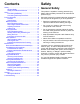
Contents Safety Safety ....................................................................... 3 General Safety ................................................... 3 Safety and Instructional Decals .......................... 4 Setup ........................................................................ 6 Connecting the Battery ....................................... 6 Connecting the Pump to the Tank ....................... 7 Product Overview .....................................................
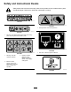
Safety and Instructional Decals Safety decals and instructions are easily visible to the operator and are located near any area of potential danger. Replace any decal that is damaged or missing. decal117-2718 117-2718 decal125-6171 125-6171 1. Piercing hazard—wear hand protection. decal119-0217 119–0217 1. Warning—shut off the engine; keep away from moving parts; keep all guards and shields in place. decal125-6156 125–6156 1. Tank drain—read the Operator’s Manual. decal125-6155 125–6155 1.
decal125-6185 125-6185 1. Engine stop 3. Engine start 2. Engine run decal125-6186 125-6186 1. Engine stop 3. Fast 2.
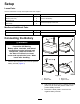
Setup Loose Parts Use the chart below to verify that all parts have been shipped. Description Use Qty. 2 2 2 1 2 Bolt (5/16 x 3/4 inch) Washer (5/16 inch) Nut (5/16 inch) Circulation hose Hose clamp Connect the battery. Connect the pump to the tank. Media and Additional Parts Description Use Qty. 1 Transfer hose Connect the mixer to the drill.
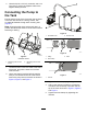
4. Use a bolt (5/16 x 3/4 inch), a washer, and a nut (5/16 inch) to mount the negative cable to the negative battery terminal. Connecting the Pump to the Tank Ensure that the frame of the fluid mixer and the frame of the tank are secured to a strong surface, with an adequate fastener through each mounting hole (Figure 4). Note: Ensure that the mixer and the tank are in a position that allows the hoses to connect them without stretching or kinking. g024043 Figure 5 1. Circulation hose 2.
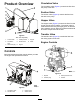
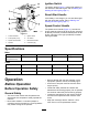
Circulation Valve Product Overview The circulation valve (Figure 9) controls the flow from the pump to the tank. Suction Valve The suction valve (Figure 9) controls the flow from the tank to the pump. Hopper Valve The hopper valve (Figure 9) controls the flow from the hopper into the mixing system. The hopper valve is most effective when it is just slightly open, as the fluid then creates a vacuum effect and draws the bentonite and other components into the flow.
Ignition Switch The ignition switch (Figure 11) allows the operator of the machine to start the engine; refer to Starting and Shutting Off the Engine (page 11). Recoil-Start Handle If the battery is not charged, you can start the engine with the recoil-start handle; refer to Starting and Shutting Off the Engine (page 11). Speed-Control Handle The speed-control handle (Figure 11) controls the engine speed and also shuts off the engine.
Fuel Safety Before starting the engine, ensure that the hopper valve and the transfer valve are both closed, and the suction valve and the circulation valve are both open (Figure 9). • Use extreme care in handling fuel. It is flammable and its vapors are explosive. • Extinguish all cigarettes, cigars, pipes, and other sources of ignition. Adding Fuel • Use only an approved fuel container.
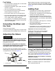
Filling the Fuel Tank During Operation Capacity: 5.4 L (5.7 US qt) 1. Park the machine on a level surface, shut off the engine, and allow the engine to cool. During Operation Safety 2. Clean around the fuel-tank cap and remove it (Figure 13). General Safety • The owner/operator can prevent and is responsible for accidents that may cause personal injury or property damage.
Starting the Engine 3. Important: Because the fluid cools the pump seal, the pump may overheat if you run the engine without fluid in the mixer. Do not run the engine without fluid in the mixer. Note: The decompression lever will stay cocked to the left and will automatically return to the original position when the recoil starter handle is pulled again. Starting the Engine using the Key Switch 1. 2. Push the decompression lever to the left (Figure 10). 4.
Mixing the Fluid that allows the dry components to enter the mixer at a faster rate. 6. WARNING If you run the engine when the mixing valves are not adjusted as directed, the pump can direct fluid out through the hopper and push the grate into the air. Note: Add the bentonite slowly to avoid clumping—1 bag in approximately 3 to 5 minutes. Open the tank cover and look to ensure that the fluid components are mixing correctly. If you see any clumps, add the components at a slower rate.
Draining the Tank To drain the tank, remove the drain plug from the side of the tank frame (Figure 8). Dispose of the used drilling fluid, as well as the unused fluid left in the tank, according to environmental regulations. Protecting the Machine from Freezing 1. Ensure that all the valves are open. 2. Rinse the tank with clean clear water and then pump it through the system, removing as much of the slurry mix in the system as possible. 3. Drain the tank; refer to Draining the Tank (page 14). 4.
Maintenance Important: Before performing any maintenance procedures, first shut off the engine and wait 5 minutes to allow all moving parts to come to a complete stop and cool. Recommended Maintenance Schedule(s) Maintenance Service Interval Maintenance Procedure After the first 25 hours • Change the engine oil. After the first 50 hours • Inspect and clean the engine-oil filter. Before each use or daily • Inspect the air-cleaner element. • Check the engine-oil level.
Lubrication Engine Maintenance Lubricating the Pump Servicing the Air Cleaner Service Interval: Every 100 hours Service Interval: Before each use or daily—Inspect the air-cleaner element. Grease Type: NLGI #1 heavy-duty EP grease Every 50 hours—Clean the air-cleaner element. Clean it more frequently in dusty operating conditions. Use a grease gun to pump grease into the grease fitting on the side of the pump (Figure 19).
Note: Be careful to prevent dirt and debris from entering the air duct inside the air-cleaner housing. 10. Slide the outer foam element over the paper element. 11. Install the air cleaner elements and ensure that they are properly positioned. 12. Install the internal wing nut 13. Securely install the cover with the other wing nut.
g038412 Figure 22 5. 6. 7. 8. 9. Remove the drain plug. Allow the oil to drain and replace the drain plug. Remove the dipstick (Figure 21) and slowly pour oil into the fill hole until the oil is between the upper and lower limit on the dipstick; refer to Checking the Engine-Oil Level (page 17). Install and secure the dipstick. Wipe up any spilled oil. Inspecting and Cleaning the Engine-Oil Filter Service Interval: After the first 50 hours Every 400 hours 1. Remove the oil-filter retaining bolt. 2.
Draining the Fuel Tank and Replacing the Outlet Fuel Filter Fuel System Maintenance Service Interval: Every 200 hours—Replace the outlet fuel filter. Servicing the Fuel System 1. Shut off the engine and wait for all moving parts to stop. Cleaning the Inlet Fuel Screen 2. Service Interval: Every 50 hours—Clean the inlet fuel screen. Place an approved container under the fuel tank to collect the fuel. 3. Remove the fuel cap (Figure 25). 1. Clean the area around the fuel cap. 2.
6. Remove and discard the O-ring (Figure 26). 7. Pull the outlet fuel filter and gasket out of the filler port (Figure 26). Electrical System Maintenance 8. Install a new outlet fuel filter and gasket through the filler port, and seat them in the fuel tank (Figure 26). Replacing the Battery 9. Install a new O-ring on the fuel shutoff lever, and install the assembly to the fuel tank using the nuts under the fuel shutoff lever (Figure 26). 10. Install the drain plug with a new gasket (Figure 25).
Checking and Cleaning the Battery Charging the Battery WARNING Service Interval: Every 100 hours—Check the battery cable connections. Charging the battery produces gases that can explode, seriously injuring you or bystanders. Keep the top of the battery clean. If the machine is stored in a location where temperatures are extremely high, the battery discharges more rapidly than if the machine is stored in a cooler location. Never smoke near the battery, and keep sparks and flames away from the battery.
Cleaning Storage Cleaning the Machine Storing the Machine Regular cleaning and washing increases the life span of the machine. Clean the machine after each use, before the dirt hardens. For storage over 30 days, prepare the machine as follows: 1. Ensure that the fuel-tank cap and oil cap/dipstick are secure to avoid getting water in the engine. Use care when using a high-pressure sprayer, because it can damage warning decals, instruction signs, and the engine.
Troubleshooting Problem The engine does not start. The engine lacks power or runs rough. Possible Cause 1. The engine On/Off switch is in the OFF position. 1. Rotate the switch to the ON position. 2. The fuel tank is empty. 3. The engine contains bad or old fuel. 2. Fill the fuel tank with fresh fuel. 3. Drain the fuel tank. Fill the fuel tank with fresh fuel. 1. The air filter is restricted. 1. Clean or replace the air-filter element(s). 2. The engine contains bad or old fuel. 2.
European Privacy Notice The Information Toro Collects Toro Warranty Company (Toro) respects your privacy. In order to process your warranty claim and contact you in the event of a product recall, we ask you to share certain personal information with us, either directly or through your local Toro company or dealer. The Toro warranty system is hosted on servers located within the United States where privacy law may not provide the same protection as applies in your country.