Form No. 3429-295 Rev A 4050 Directional Drill Model No. 23898—Serial No. 315000001 and Up Model No. 23899—Serial No. 315000001 and Up Register at www.Toro.com.
It is a violation of California Public Resource Code Section 4442 or 4443 to use or operate the engine on any forest-covered, brush-covered, or grass-covered land unless the engine is equipped with a spark arrester, as defined in Section 4442, maintained in effective working order or the engine is constructed, equipped, and maintained for the prevention of fire. and warranty. Replacements may be ordered through the engine manufacturer.
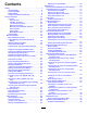
Contents Replacing the Pipe Holder ................................ 69 Maintenance ........................................................... 70 Recommended Maintenance Schedule(s) ........... 70 Pre-Maintenance Procedures .............................. 72 Pre-Maintenance Safety ................................... 72 Opening the Front Hood ................................... 72 Opening the Rear-Access Door ........................ 72 Using the Cylinder Lock ....................................
Safety Servicing the Hydraulic Fluid ............................ 98 Drilling-Fluid Pump Maintenance ....................... 102 Servicing the Drilling-Fluid-Pump Oil .............. 102 Preparing the Drilling-Fluid System for Cold Weather ...................................................... 104 Cab Maintenance ............................................... 106 Changing the Cab Air Filter ............................. 106 Filling the Windshield-Washer Fluid Tank ..........................................
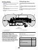
Tramming Safety • Move slowly when using the pendant for tramming. • Use care when loading or unloading the machine You move the machine to and from the work site with the use of a travel pendant. When tramming (moving the machine with the pendant), observe the following safety precautions: onto a trailer. • Watch for traffic when crossing roadways. • Check for overhead clearances (i.e., doorways, branches, electrical wires) before tramming under any objects and do not contact them.
Drilling Safety Drilling Danger Zone • Always lower the pipe loading guard before drilling The danger zone is the area within and around the machine where a person is exposed to the risk of injury. • • • • (Figure 4). Always engage the exit side lockout before operating. Keep bystanders and children out of the operating area. Stop operating the machine if anyone enters the drilling danger zone. Ensure that no one approaches a pipe while it is spinning.
Reclaimed water, irrigation, and slurry lines Purple Temporary survey markings Pink Proposed excavation limits White Gas Line Safety WARNING If you damage a gas line, an immediate explosion and fire hazard could occur. Leaking gas is both flammable and explosive and may cause serious injury or death. Electrical and Communication Line Safety • Do not smoke while operating the machine. WARNING • Shut off the machine and remove the key.
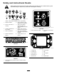
Safety and Instructional Decals Safety decals and instructions are easily visible to the operator and are located near any area of potential danger. Replace any decal that is damaged or missing. decalbatterysymbols Battery Symbols Some or all of these symbols are on your battery 1. Explosion hazard 6. Keep bystanders a safe distance from the battery. 2. No fire, open flame, or smoking. 7. Wear eye protection; explosive gases can cause blindness and other injuries 3.
decal125-1623 125-1623 1. Forward left track/forward rotary 11. Wrench makeup (for upper wrench) 2. Reverse left track/reverse rotary 12. Raise pipe elevator 3. Drilling fluid pump on 13. Lower pipe elevator 4. Forward right track/forward carriage 14. Reverse cam rotation 5. Reverse right track/reverse carriage 15. Forward (toward operator) cam rotation 6. Tighten lower wrench (stationary wrench) 16. Tighten pipe grip 7. Loosen lower wrench (stationary wrench) 17. Loosen pipe grip 8.
decal125-6107 125-6107 decal125-6109 1. Crushing hazard of hand and foot—keep hands and feet away. 125-6109 1. Electrical shock hazard—when the Zap-Alert system is activated, do not leave the operator’s position or touch the ground and the machine at the same time. decal125-6110 125-6110 1. Crushing hazard—do not stand under any part of the machine. decal125-6108 125-6108 1. Thrown object hazard—read the Operator’s Manual.
decal125-6111 125-6111 1. Stake up 6. Stake up 2. Stake down 7. Stake spin counterclockwise 8. Stake down 3. Stake spin counterclockwise 4. Stake spin clockwise 5. Left stake 9. Stake spin clockwise 10. Right stake decal125-6114 125-6114 1. Stored energy hazard—do not use tools; read the Operator’s Manual. decal125-6115 125-6115 1. Crushing hazard—deploy cylinder locks before performing maintenance. decal125-6113 125-6113 1. Warning—read the Operator’s Manual. 4.
decal125-6116 125-6116 1. Falling hazard—do not move the machine when someone is in the operator’s position. decal125-6118 125-6118 1. Crushing hazard, machine movement—read the Operator’s Manual. decal125-6119 125-6119 1. Entanglement hazard—stay away from moving objects. decal125-6117 125-6117 1. Falling hazard—do not stand on the machine while it is moving. decal125-6124 125-6124 1. Center the pipe joint between the upper and lower wrenches.
decal125-6120 125-6120 1. Lower drill carriage 4. Lower left stabilizer 2. Raise drill carriage 5. Raise right stabilizer 3. Raise left stabilizer 6. Lower right stabilizer decal125-6125 125-6125 1. Warning—read the Operator’s Manual. 2. Explosion hazard; electrical shock hazard—do not dig before calling local services. decal125-6123 125-6123 3. Press to apply thread-joint compound. 1. Load pipes from the back row first. 4.
decal138-7085 138-7085 decal125-6126 1. Warning—read the Operator’s Manual. 9. Rotate the drill spindle clockwise (drill mode I) 125-6126 1. Entanglement hazard—stay away from moving parts. 2. Explosion hazard; 10. Rotate the drill spindle electrical shock counter clockwise (drill hazard—do not dig; call mode I) your local utility company. 3. Drilling-fluid pump—On/Off 11. Cruise Control—set/release 4. Drilling fluid—increase 12. Carriage thrust speed—high 5. Drilling fluid—decrease 13.
decal125-6129 125-6129 1. Hot surface—stay away from hot surfaces. decal125-6135 125-6135 decal125-6137 125-6137 decal125-6131 125-6131 1. Warning—stay away from the area shown (at least 3 m or 10 ft away) while in operation.
decal125-6130 125-6130 1. Warning—read the Operator’s Manual; stay away from the area shown (at least 3 m or 10 ft away from the front and rear of the machine and 1.8 m or 6 ft away from the side of the machine) while in operation. decal125-6139 125-6139 1. Lift point and tie-down point decal125-6141 125-6141 decal125-6140 125-6140 1. Rotate the chair. 16 1. Engine—heating light 4. Engine—start 2. Engine—stop 5. Drill-pendant receptacle 3. Engine—run 6.
decal125-6142 125-6142 1. Exit-side lockout—reset light 14. Work lights—Off 2. Exit-side lockout—drill-enabled light 15. Press and hold to increase the engine speed. 3. Transmitter-battery-status light 16. Engine speed 4. Engine—start 17. Press and hold to decrease the engine speed. 5. Press down to shut off the engine; pull up to start the engine. 18.
decal125-6151 125-6151 1. Do not exceed loads of 2,268 kg (5,000 lb). decal138-7084 138-7084 1. Exit-side lockout—reset light 15. Rotate the cam forward or backward (drill mode II). decal125-6152 2. Press down to shut off the 16. Rotate the cam forward or engine. backward (drill mode I). 125-6152 1. Move the seat forward and backwards. 3. Pull up to start the engine. 17. Move to the next or previous step in SmartTouch™ mode. 18. Retract the pipe gripper 4. Rotate the drill spindle arm.
decal125-6157 125-6157 1. Disconnect the battery power. 3. On/Start 2. Off/Stop 4. Read the Operator’s Manual.
Decals 125-6158 and 138-7086 are for the Cab Models only decal138-7086 138-7086 1. Engine—start 16. Zap-Alert system triggered 2. Raise the pipe elevator. 17. Unlock exit-side lockout 3. Lower the pipe elevator. 18. Reset exit-side lockout 4. Tighten or loosen the pipe 19. Exit-side grip. lockout—unlock/reset light 5. Rotate the cam forward or 20. Engage drive movement and setup functions backward (drill mode II). 6. Rotate the cam forward or 21.
decal125-6158 125-6158 1. Engine—start 2. Press down to shut off the engine. 13. With the trigger released, rock forward to rotate the basket toward the pipe cam; rock backwards to rotate the basket toward the drill frame. 14. With the trigger released, the upper button closes the pipe gripper; the lower button opens the pipe gripper. 3. Pull up to start the engine. 15.
decal125-6694 125–6694 1. Tie down location decal125-6180 125-6180 1. Entanglement hazard—stay away from moving parts. decal125-8473 125–8473 1. Explosion hazard—wear eye protection. 3. Fire hazard—keep open flames away. 2. Caustic liquid/chemical burn hazard—rinse affected area and seek medical assistance. 4. Poison hazard—do not tamper with the battery. decal125-6183 125-6183 1. Press the operator presence switch to enable machine movement. decal125-8483 125–8483 1.
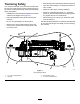
Product Overview g034670 Figure 5 1. Drill carriage 6. Rear hood 2. Zap-alert strobe 7. Rear-access door 8. Right stabilizer 3. Cab 4. Monitor 5. Thrust frame 9. Front hood 10.
g034671 Figure 6 1. Pipe holder 4. Left stabilizer 2. Pedestrian safety bar 5. Rear-control panel 3. Stake-down plate 6.
g034672 Figure 7 1. Drill carriage 5. Cab 2. Drill spindle 6. Upper wrench (makeup/breakout wrench) 3. Thrust frame 7. Lower wrench (stationary wrench) 4.
Controls Operator-Controls Covers Refer to the following sections for the appropriate machine controls: The covers protect the operator controls from adverse weather conditions, such as rain, wind, sunlight, etc. Remove them before using the machine and replace them before leaving the machine for the day. Each cover is secured with 2 screws as shown in Figure 9. • The Software Guide for this machine.
Exit-Side Lockout—Drill-enabled Light This light (Figure 12) illuminates green when the exit-side-lockout feature has been turned off and reset and the machine is ready to drill. Exit-Side Lockout—Reset Switch Press this switch (Figure 12) to enable drilling operation when the reset light illuminates. Transmitter-Battery-Status Light This light (Figure 12) illuminates red when the battery on the exit-side-lockout transmitter is too low to transmit.
4-Button Joysticks • Press the trigger to enable the wrench controls. • Release the trigger to enable the pipe-loader controls. Left Joystick Toggle Switch • Left trigger pressed—rock the switch forward to rotate the upper wrench (makeup/breakout wrench) clockwise to loosen a joint; rock the switch rearward to rotate the upper wrench (makeup/breakout wrench) counterclockwise to tighten a joint.
Right Joystick Trigger Note: The joystick controls vary depending on the Press and hold the trigger to move the drill carriage at high speed up or down the drill frame. control mode you select. There are 2 control modes: Mode I and Mode II; refer to the Software Guide for this machine to set the control mode. Toggle Switch Rock the switch forward to increase the flow rate of the drilling fluid; rock the switch rearward to decrease the flow rate of the drilling fluid.
7 or 8-Button Joysticks Joysticks in Setup Mode The machine must be in setup mode (Figure 12) and you must be in the seat to use these functions. g225942 Figure 15 Joysticks – Setup Mode 1. Lower the left stake down 5. Lower the right stake down 2. Rotate the left stake clockwise 6. Rotate the right stake clockwise 3. Raise the left stake up 7. Raise the right stake up 4. Rotate the left stake counter clockwise 8.
Left Joystick g226145 Figure 16 Left Joystick in DRILL mode 1. Raise the elevator 6. Go to the next step in SmartTouch™ mode 2. Lower the elevator 7. Retract the pipe gripper arm 3. Open / Close the pipe gripper 8. Extend the pipe gripper arm 4. Rotate the cam assembly 9. Apply tread-joint compound 5. Go to the previous step in SmartTouch™ mode g226143 Figure 17 Left Joystick — Directional Controls 1. Rotate the drill spindle counter clockwise (Drill Mode II) 3.
Right Joystick The joystick controls vary depending on the control mode you select when powering up the machine. There are 2 control modes: Drill Mode I and Drill Mode II; refer to the Control-Select Screen in the Software Guide for information on setting the control modes. g226146 Figure 18 Right Joystick 1. Turn the mud on or off 4. Open and Close the rear wrench 2. Increase the mud flow momentarily 5. Open and close the front wrench 3. Decease the mud flow momentarily 6.
Exit-Side-Lockout System The exit-side-lockout system provides the individuals working around the machine with a means to disable the drill pipe from rotating and thrusting. For more information and instructions, refer to the Operator’s Manual for the Exit-side-lockout system. Rear Control Panel g022115 Figure 21 1. Engine-off position 3. Engine-start position 2. Engine-run position • Engine-off position—turn the key to this position to stop the engine.
Drive Pendant Drill Frame and Stabilizer Controls Refer to Figure 20 for the location of the drive pendant. g023839 Figure 22 1. Drill-frame tilt lever 3. Right-stabilizer lever 2. Left-stabilizer lever g021855 Figure 23 Stabilizer Levers Use the stabilizer levers to raise and lower the stabilizers. 1. Engine-speed switch 4. Drive-speed switch 2. Drive-direction joystick 5. Operator-presence switch 3.
Drive-Speed Switch The switch sets the speed at which the machine will travel. Move the switch up for high speed or down for low speed. Operator-Presence Switch Press and hold this button to enable the other controls on the drive pendant. The machine will stop moving if you release this button. Drill Pendant WARNING Only an authorized person(s) should operate the drill pendant. Personal injury, harm to others, or damage to the machine could occur if this pendant is misused.
Drilling Fluid and Wrench-Control Switch Pipe-Grip-Control Switch When this switch is connected to the front drill-pendant receptacle, move it to control the drilling-fluid flow or the wrench operation. When this switch is connected to the front drill-pendant receptacle, move it to control the pipe grip. • Move the switch to the left to turn the drilling fluid • Move the switch forward to tighten the grip on the pipe. to the ON position.
Battery-Disconnect Switch Stake-Down Levers Open the rear compartment to access the BATTERY -DISCONNECT switch. Turn the BATTERY -DISCONNECT switch to the ON or OFF position to perform the following: • To energize the machine electrically, rotate the BATTERY -DISCONNECT switch clockwise to the ON position (Figure 26). • To de-energize the machine electrically, rotate the BATTERY -DISCONNECT switch counterclockwise to the OFF position (Figure 26). g021835 Figure 25 1. Left-stake-raise/lower lever 2.
Operation • Do not store the machine or fuel container where Determine the left and right sides of the machine from the normal operating position. • If you spill fuel, do not attempt to start the engine; there is an open flame, spark, or pilot light, such as on a water heater or other appliance. avoid creating any source of ignition until the fuel vapors have dissipated.
After completing the operation, you need to disconnect and clean the machine and load it on the trailer; refer to Finishing the Job (page 66). drilling fluid or “mud”, through the drill pipe and out the drill bit. The drilling fluid lubricates the bit, helps to hold the bore open while drilling, and mixes with the spoils, flushing them out of the bore through the entry point.
– Electrical power lines DANGER Contacting underground hazards with the machine while drilling or reaming can cause explosion, electrocution, breathing problems, severe trauma, and death to you or bystanders. DANGER Drilling into an electric power line will cause the machine to become electrified and may electrocute you or any bystanders.
– Crystalline silica and other dust If you will be drilling through or cutting concrete, sand, or other substances that create dusts or fumes, you need to ensure that you and all workers wear breathing protection to protect your lungs from the dust.
Planning the Bore Path Before setting up the job site, you need to plan the bore path, including the following: g034676 Figure 27 1. Bore entry 4. Obstacle 2. Beginning-of-bore-at-depth point 5. End-of-bore-at-depth point and bore exit 3. Bore depth • Bore entry you will need to determine the distance from the end-of-bore-at-depth location needed for steering the drill to the surface, typically 9 to 15 m (30 to 50 ft) from the end-of-the-bore-at-depth point.
g021765 Figure 28 1. 20 cm (8 inches) This flexibility is often rated in materials as a minimum bend radius, which is the radius of the circle formed if the material or pipes, connected together, were bent to form a giant circle. The minimum radius of a circle made with the pipe used with this machine is 33 m (108.2 ft). g034678 • Entry pitch Figure 30 The entry pitch is the angle at which the machine enters the ground.
Note: The depths given in the following table are for 3 m (10 ft) of combined drill head and pipe. As you steer up, the pitch of the steered section will change and can be monitored with the receiver. Use the following table to identify how many lengths of pipe will be necessary to insert and steer to the beginning point and help you choose an entry point.
Given the above information, you can calculate the number of rods required to reach your beginning point at the appropriate depth. Toro recommends that you start the entry point the same distance back from your beginning-at-depth point as the length of pipes you will need to reach that point. This will ensure that you have enough extra space so you will not need to over-steer and damage the pipes.
• Insert the first 3 m (10 ft) of drill bit/pipe into the The following example illustrates the process given an installation using the machine at an 18% pitch on level ground: ground with no steering. The end of the drill bit will be 53 cm (21 inches) deep (Figure 32). g034679 Figure 32 1. 18% pitch 3. 96 cm (38 inches) 5. 119 cm (47 inches) 2. 53 cm (21 inches) 4. 114 cm (45 inches) 6. 10.
Preparing the Job Site and the Machine Checking the Safety-Interlock Switches Before drilling, prepare the job site and the machine as follows: Checking the Operator Presence Safety-Interlock Functions on the Operator Platform • Mark and prepare the bore path Marking and Preparing the Bore Path (page 47). • Test the Zap-Alert system; refer to Testing the Zap-Alert System (page 48). • Load the drill pipes into the pipe holder if 1. Start the engine. 2.
Testing the Zap-Alert System 3. Connect an alligator clip from the Zap-alert tester to the grounding stud on the Zap-alert system (Figure 33). The Zap-Alert system is an electric strike sensing device on the machine that triggers a strobe light and audible alarm in the event that the drill bit, reamer, or stake breaks into an energized power line. In the event of an electric strike, the machine will become energized, setting off the alarm.
7. Disconnect the alligator clips from the grounding stud and the machine. 8. Store the grounding stake in the holder on the operator platform as shown in Figure 34. g021838 Figure 34 1. Grounding stake If either the audible alarm or the strobe light fail to trigger when you pressed the TEST button, have them repaired before drilling with the machine. Mounting a Fire Extinguisher Mount your fire extinguisher below the operator seat (Figure 35).
Loading Drill Pipes into the Pipe Holder Before using the machine, fill the pipe holder with up to 40 drill pipes. g034681 Figure 36 1. Pipe 2. Male end 1. Remove the clevis pins from the pipe holder (Figure 36). 2. Insert the pipes from the top with the male threaded pipe ends toward the front of the machine (Figure 36). 3. Install the clevis pins before drilling. 3. Clevis pins Note: Before drilling, check the condition of the pipes and replace any that are bent or damaged.
Filling the Fuel Tank WARNING Fuel is harmful or fatal if swallowed. Long-term exposure to vapors can cause serious injury and illness. • Avoid prolonged breathing of vapors. • Keep face away from nozzle and gas tank or conditioner opening. • Keep fuel away from eyes and skin. Fuel Tank Capacity 208 L (55 U.S. gallons) Fuel Specification Use only clean, fresh diesel fuel or biodiesel fuels with ultra low (<15 ppm) sulfur content. The minimum cetane rating should be 40.
2. Using a clean rag, clean the area around fuel-tank cap. 3. Remove the cap from the fuel tank (Figure 37). To stop the engine, turn the ignition key to the OFF position. In an emergency, you can also stop the engine and all processes by pressing the ENGINE-STOP button on either the drive pendant or the control panel. Driving the Machine 1. Start the machine, and ensure that the stake-down augers are removed from the ground. 2.
frames and the stake-down plate to the trailer (Figure 39). WARNING The machine can slip and fall from a trailer or ramp, crushing anyone caught beneath it and causing serious injury or death. • Keep all bystanders away from the machine and trailer. • Ensure that the trailer and ramp are not slippery and are free of ice, grease, oil, etc. • Move the machine onto the ramp at slow speed with the engine at slow speed. • Ensure that you have the machine centered on the ramp and trailer. g034682 Figure 39 1.
g025651 Figure 42 1. Rear platform latch g034674 Figure 40 1. Screw 4. Deploying the Zap-Alert System 2. Cover Lower the pedestrian safety bar and secure it in place (Figure 41). The Zap-alert system is an electric strike-sensing device on the machine that triggers a strobe light and an audible alarm whenever the drill bit, reamer, or stake breaks into an energized power line. In the event of an electric strike, the machine will become energized, setting off the alarm.
3. DANGER If the Zap-alert system activates while drilling, the machine, except for the operator platform, will become energized. If you step off the operator platform or if someone touches the machine or wet ground near the machine or in the bore, you or the one who touched the machine could be electrocuted, causing serious injury or death. • Test the Zap-alert system before drilling. • Deploy the grounding stake before drilling. Ensure that the stake is fully inserted into moist soil.
5. Lower the rear stabilizers until they contact the ground firmly, or until the desired entry angle is achieved (Figure 46). Connecting to a Drilling-Fluid Source Note: The rear of the tracks should just start to lift off the ground. When drilling and reaming, you pump a mixture of bentonite clay, water, and sometimes other ingredients, collectively called drilling fluid or “mud”, through the pipe and into the bore.
Positioning the Cab (Model with Cab only) Positioning the Cab for Drilling Operation 1. Push back on the SWING-ROCKER switch (until the cab stops) to swing the cab to the DRILL position (Figure 50). g023513 Figure 48 1. Cam-lock levers 2. 2. Pump-inlet cap Insert the hose from the mixing system over the pump inlet, and secure it with the cam-lock levers. g025987 Setting up the Pump to Use a Natural Water Source Figure 50 1.
Opening the Door (Model with Cab only) Operating the Air Conditioning and Heating (Model with Cab only) Open the door from the outside by pulling on the handle, and swing the door to the left (Figure 51). Air Conditioning the Cab 1. Push the AIR-CONDITIONING switch to the right to turn the air conditioning to the ON position (Figure 53). g023685 Figure 51 1. Door handle g023687 Figure 53 Open the door from the inside by pulling the knob backward and pushing the door to the outside (Figure 52). 1.
Operating the Windshield Wipers (Model with Cab only) During Operation Changing the Windshield-Wiper Speed General Safety During Operation Safety • The owner/operator can prevent and is responsible for accidents that may cause personal injury or property damage. Turn the WINDSHIELD-WIPER knob (Figure 54) to the right increase the speed of the windshield wipers, or turn the knob to the left to decrease the speed.
Drilling the Bore Slope Safety When operating the machine on a slope, the operator must account for many variables, such as the amount, distribution, and height of the load; the stability of the ground; uneven terrain and obstacles; and the condition of the brakes. These and other variables make it impractical to designate the maximum angle at which the operator can safely use the machine for all slopes and situations. Starting the First Pipe 1.
Setting up the Drill Head and the Tracking System The drill head consists of 2 parts, the drill bit and the sonde housing (Figure 57). g023076 Figure 57 1. Sonde housing g023059 Figure 56 1. Drill spindle 10. 2. Pipe Drill bits vary in size and type to meet the various soil conditions that you may need to drill through.
Installing the Drill Head 1. Using the exit-side-lockout transmitter, activate the exit-side lockout to disable the thrust and rotation of the carriage. WARNING If the drill rotates or extends while you or others are manually working on the drill bit or pipe in front of the machine, the worker could get caught in the bit or pipe, causing serious injury, amputation, or death.
Note: The drilling fluid will automatically shut off when you activate the upper wrench (makeup/breakout wrench). transmitter (the OK-to-Drill light on the control panel should illuminate); press the exit-side-lockout, RESET switch on the control panel. 5. 3. Using the lower wrench (stationary wrench), clamp the lead bar, and tighten the drill spindle to full-seat threads. 6. Double check the drill head and bit to ensure that the fluid ports are clean and free from obstructions. 7.
Steering the Drill Head 1. The drill bit is shaped like a wedge, angled from one side of the bit to the other. When you push the bit through the soil without rotating it, it will veer toward the direction the wedge is pointing. When you rotate the pipe and drill head, it bores through the soil in a straight path. Increase the flow of the drilling fluid for a few seconds without drilling, then attempt to continue drilling forward. Note: This may loosen the obstruction and allow you to push past it. 2.
Removing Drill Pipes pack the sides of the bore, maintaining the bore opening. • Fluted reamer—Use this reamer in hard clay and rocky soils; it combines the features of the other 2 reamers. 1. Using the exit-side-lockout transmitter, enable the exit side lockout. 2. Install a drill-pipe wiper around the pipe and into the retaining bracket on the front of the machine.
10. Release the upper wrench (makeup/breakout wrench). 1. Using the exit-side-lockout transmitter, enable the exit side lockout. 11. Pull back the carriage approximately 12.7 mm (0.5 inch). 2. Note: This will allow the carriage to float, and will not damage the pipe threads. After the reamer has cleared the ground, if you have not already done so, disconnect the product being installed from the reamer. 3.
Adjusting the TJC-Spray Volume • Install the controls covers; refer to Operator Platform (page 26). 1. • Flush the drilling fluid out of the drilling-fluid pump with water or antifreeze. Loosen the jam nut on the adjustment bolt located on top of the TJC-applicator piston (Figure 64). Important: The drilling-fluid pump may be damaged if the drilling-fluid dries up in the pump.
Moving a Disabled Machine Filling the TJC Applicator 1. Stop the machine and stop the engine. 2. Open the stake-down-guard door. 3. Loosen the wing nuts securing the cover straps to the machine (Figure 65). Whenever the machine is stopped and the engine is not running, the hydrostatic brakes automatically engage. Do not attempt to tow the machine if it cannot move under its own power. If possible, repair the machine at the site.
Replacing the Pipe Holder 1. Ensure that the 2 upper pins and the 2 lower pins are installed to secure the pipe inside the pipe holder (Figure 67). g023867 Figure 67 1. Upper pins 2. Lower pins 2. Remove the lower, outer pins on the pipe holder (Figure 68). 3. With a hoist capable of lifting 2,260 kg (5,000 lb), remove the pipe holder. g023865 Figure 68 1. Front pin 2.
Maintenance WARNING Failure to properly maintain the machine could result in premature failure of machine systems, causing possible harm to you or bystanders. Keep the machine well maintained and in good working order as indicated in these instructions. Note: Determine the left and right sides of the machine from the normal operating position. Place a service tag on the machine when maintenance procedures are being performed. Replace all covers and guards after you service or clean the machine.
Maintenance Service Interval Maintenance Procedure Every 500 hours • Inspect the fuel lines and connections. • Check the stakedown planetary-drive oil level (Also, check if external leakage is observed). • Check the rotary motor planetary-drive oil level (Also, check if external leakage is observed). • Check the thrust motor planetary-drive oil (or yearly, whichever comes first). • Check the gearbox drive oil (or yearly, whichever comes first).
Pre-Maintenance Procedures Pre-Maintenance Safety • Before adjusting, cleaning, repairing, or leaving the machine, do the following: – Move the machine on a level surface. – Shut off the machine. – Turn the battery-disconnect switch to the OFF position. – Wait for all moving parts to stop. – Allow machine components to cool before performing maintenance. g034686 Figure 70 • If possible, do not perform maintenance while the 1. Hood latch engine is running. Keep away from moving parts.
g023293 Figure 73 g034689 Figure 72 1. Rear-access door handle 1. Cotter pin 4. Clevis pin 2. Cylinder lock 5. Lift cylinder 3. Lift cylinder rod Using the Cylinder Lock Removing and Storing the Cylinder Lock WARNING The thrust frame may lower when it is in the raised position, causing serious injury or death. 1. Start the engine. 2. Lower the thrust frame to the fully lowered position. Install the cylinder lock before performing maintenance that requires the thrust frame to be raised. 3.
Lubrication Greasing the Machine Service Interval: Before each use or daily (Grease immediately after every washing). Grease type: General-purpose grease. 1. Park the machine on a level surface, stop the engine, and remove the ignition key. 2. Clean the grease fittings with a rag. 3. Connect a grease gun to each fitting. 4. Pump grease into the fittings until grease begins to ooze out of the bearings (approximately 3 pumps). 5.
g034479 Figure 82 Stabilizer cylinder and foot (repeat on other side) g034475 Figure 79 Front pipe-loader cam area (6 fittings) g023617 Figure 83 Carriage-roller bearings (operator’s side shown; repeat on other side) g034474 Figure 80 Rear pipe-loader cam area (6 fittings) g023610 Figure 84 Gearbox float (operator’s side shown; repeat on other side) g034473 Figure 81 Hydraulic cylinder and wrench assembly 75
Engine Maintenance Engine Safety • Shut off the engine before checking the oil or • adding oil to the crankcase. Do not change the governor speed or overspeed the engine. Cleaning the Crankcase-Vent Tube g023611 Figure 85 Stakedown shaft (left side shown; repeat on right side) Service Interval: Before each use or daily—Check the crankcase-vent tube and clean it if necessary. 1. Park the machine on a level surface, stop the engine, and remove the ignition key. 2. Open the front hood. 3.
Cleaning the Dust Valve • Check the air-cleaner body for damage which could cause an air leak. Replace it if it is damaged. Check the whole intake system for leaks, damage or loose hose clamps. Also, inspect the rubber intake hose connections at the air cleaner and the turbo to make sure that the connections are complete. Service Interval: Every 50 hours 1. Park the machine on a level surface, stop the engine, and remove the ignition key. 2.
5. Pull the 4 latches for the air-cleaner cover outward (Figure 88). into the intake tract. This cleaning process prevents debris from migrating into the intake when the primary filter is removed. 4. Using the air-filter handles, remove the primary filter from the air-cleaner cover (Figure 89). Important: Do not clean the used filter. g023655 Figure 88 1. Air-cleaner cover latches 6. Pull the air-cleaner cover away from the filter housing and remove the cover. 7.
Checking the Engine-Oil Level Servicing the Engine Oil and Filter Service Interval: Before each use or daily—Check the engine oil level. The engine is shipped with oil in the crankcase; however, check the oil level before and after you first start the engine. Crankcase capacity: 7.5 L (7.9 US qt) with the filter. 1. Park the machine on a level surface, stop the engine, and remove the ignition key. 2. Open the front hood. 3. Remove the dipstick (Figure 91), and wipe it clean.
6. Fill the new oil filter with the specified engine oil. 7. Apply a thin layer of the specified engine oil to the seal of the oil filter. 8. Align the oil filter to the oil-filter adapter, and rotate it clockwise until the seal of the oil filter contacts the oil-filter adapter (Figure 93). Important: Do not use an oil filter strap wrench to install the new oil filter. The wrench can dent an oil filter and therefore cause a leak. 9. Hand tighten the oil filter an additional 1/2 turn (Figure 93). 10.
6. Place the drain hose back into the original position (Figure 94). 7. Change the engine oil filter; refer to Changing the Engine-Oil Filter (page 80). 8. Remove the oil-fill cap from the filler neck by pulling the cap upward. Fuel System Maintenance DANGER Under certain conditions, diesel fuel and fuel vapors are highly flammable and explosive. A fire or explosion from fuel can burn you and others and can cause property damage.
5. Note: If the fuel-water separator has any water or sediment, also drain the water and sediment from the fuel tank; refer to Draining Water from the Fuel Tank (page 82). Priming the Fuel System When clean fuel appears, rotate the drain valve clockwise until it is closed. • You drained water from the fuel filter. Note: Prime the fuel system whenever any of the following occurs: • You replaced the fuel filter. Note: Do not overtighten the drain valve. 6.
Replacing the Secondary Fuel Filter WARNING The fuel system is under high pressure. Bleeding the system without proper precautions and training could result in injury to you from injected fluid or fire or explosion. Read the engine owner’s manual for the proper bleeding procedure or contact your Authorized Toro Dealer. 1. Park the machine on a level surface, stop the engine, and remove the ignition key. 2. Open the front hood; refer to Opening the Front Hood (page 72). 3.
Checking the Fuel Lines and Connections Electrical System Maintenance Service Interval: Every 500 hours/Yearly (whichever comes first)—Inspect the fuel lines and connections. Battery Safety • Turn off the battery-disconnect switch before Inspect the fuel lines and connections for deterioration, damage, or loose connections. repairing the machine. • Charge the battery in an open, well-ventilated area, away from sparks and flames. Unplug the charger before connecting or disconnecting the battery.
Charging the Battery WARNING A battery contains sulfuric acid, which can cause serious burns; and it can produce explosive gases. WARNING Charging the battery produces gasses that can explode. • Avoid contact with skin, eyes, or clothing; flush affected areas with water. Do not smoke near the battery, and keep sparks and flames away from the battery. • If taken internally, drink large quantities of water or milk. Do not induce vomiting. Seek medical attention immediately.
Battery-charger Table Charger setting Charging time 4 to 6 amperes 30 minutes 25 to 30 amperes 10 to 15 minutes 8. When the battery is fully charged, unplug the charger from the electrical source, then disconnect the charger leads from the battery posts (Figure 100). Jump-Starting the Machine g023838 Figure 101 WARNING Jump-starting the battery can produce gasses that can explode. 1. Ground point (unpainted bolt) 4. Cover 2. Jumper-cable clamp (negative) 5.
Drive System Maintenance Checking the Oil Level for the Stakedown Planetary Drive Service Interval: After the first 100 hours—Check the stakedown planetary-drive oil level (Also, check if external leakage is observed). Every 500 hours—Check the stakedown planetary-drive oil level (Also, check if external leakage is observed). Oil specification: SAE 85W-140 API classification level GL4 Planetary-drive oil capacity: approximately 1.2 L (2.
Changing the Oil for the Tracks Planetary Drive Service Interval: After the first 250 hours—Change the planetary-drive oil. Every 800 hours—Change the planetary-drive oil (or yearly, whichever comes first). Note: Change the oil when it is warm, if possible. 1. Park the machine on a level surface. 2. Clean the area around the oil-level plug (Figure 103). 3. Rotate the planetary drive until the oil-drain plug is directly below the oil-level plug (Figure 103). 4. Stop the engine and remove the key. 5.
Checking the Oil Level for the Rotary Motor Planetary Drive Checking the Oil for the Thrust Motor Planetary Drive Service Interval: After the first 100 hours—Check the rotary motor planetary-drive oil level (Also, check if external leakage is observed). Service Interval: After the first 100 hours—Check the thrust motor planetary-drive oil. Every 500 hours—Check the thrust motor planetary-drive oil (or yearly, whichever comes first).
Checking the Oil for the Gearbox Drive Changing the Oil for the Gearbox Drive Service Interval: After the first 100 hours—Check the gearbox drive oil. Service Interval: After the first 100 hours—Change the gearbox-drive oil. Every 500 hours—Change the gearbox-drive oil (or yearly, whichever comes first). Every 500 hours—Check the gearbox drive oil (or yearly, whichever comes first). Note: Change the oil when it is warm, if possible. Oil specification: SAE 85W-140 API classification level GL4 1.
3. Remove the 2 bolts and nuts on the carriage guard (Box B of Figure 107). Servicing the Tracks 4. Remove the 2 bolts and nuts on the side of the carriage guard (Box C of Figure 107). Service Interval: Before each use or daily—Check the track tension. 5. Slide the carriage guard forward (Box D of Figure 107). 6. Remove the 6 bolts on the gearbox (Box E of Figure 107). 7. Remove the cover on the gearbox and syphon the oil out (Box F of Figure 107). 8.
Loosening the Track Tension Cooling System Maintenance If the track seems tight, loosen the track tension as follows: 1. Park the machine on a level surface, stop the engine, and remove the ignition key. Coolant specification: 50/50 solution of ethylene-glycol antifreeze and water or equivalent 2. Remove dirt and debris found around the track-tension grease valve (Figure 109). Engine and Radiator coolant capacity: 16.8 L (17.
Cooling System Safety • Swallowing engine coolant can cause poisoning; keep it out of reach of children and pets. • Discharge of hot, pressurized coolant or touching a hot radiator and surrounding parts can cause severe burns. – Always allow the engine to cool at least 15 minutes before removing the radiator cap. – Use a rag when opening the radiator cap, and open the cap slowly to allow steam to escape. g023842 Checking the Coolant Level in the Radiator Figure 110 1.
Draining the Coolant from the System Checking the Condition of Cooling-System Components Important: Do not pour coolant onto the ground or into an unapproved container that can leak. Service Interval: Every 300 hours/Yearly (whichever comes first) 1. Park the machine on a level surface, stop the engine, and remove the ignition key. Check the condition of the cooling system for leaks, damage, dirt, and loose hoses and clamps. Clean, repair, tighten, and replace the components as necessary. 2.
Flushing the Cooling System F. Engine and radiator coolant capacity: 16.8 L (17.7 US qt) Clean the threads on the drain plug and apply 3 layers of PTFE sealing tape. G. Close the drain plug. 1. Park the machine on a level surface, stop the engine, and remove the ignition key. 2. Condition the cooling system as follows: A. Ensure that the coolant is drained from the radiator and that the drain plug is closed; refer to Draining the Coolant from the System (page 94). B.
Filling the System with Coolant 4. Important: You must fill the cooling system properly to prevent air locks in the cooling passages. Failing to vent the cooling system properly can severely damage the cooling system and engine. Fill the radiator with coolant until the fluid level is up to the bottom of the filler neck (Figure 116). Note: The coolant capacity of both the engine and the radiator is 16.8 L (17.7 US qt).
Belt Maintenance Checking the Tension of the Belt Service Interval: Every 1,000 hours Servicing the Engine-Drive Belt WARNING 1. Park the machine on a level surface, stop the engine, and remove the ignition key. 2. Open the front hood. 3. Align a straight edge over the drive belt and across the pulleys as shown in Figure 117. Contacting a rotating belt can cause serious injury or death. Stop the engine and remove the ignition key before working near belts.
Adjusting the Tension of the Belt 1. Park the machine on a level surface, stop the engine, and remove the ignition key. 2. Open the front hood. 3. Loosen the nut and bolt at the pivot point for the alternator (Figure 118). Hydraulic System Maintenance Hydraulic System Safety • Seek immediate medical attention if fluid is injected into skin. Injected fluid must be surgically removed within a few hours by a doctor.
temperature or if the engine has not yet been started for the day. High Viscosity Index/Low Pour Point Anti-wear Hydraulic Fluid, ISO VG 46 (cont'd.) Pour Point, ASTM D97 Industry Specifications: -6° C (-42° F) Vickers I-286-S (Quality Level), Vickers M-2950-S (Quality Level), Denison HF-0 Note: Many hydraulic fluids are almost colorless, making it difficult to spot leaks. A red dye additive for the hydraulic system oil is available in 20 mL (2/3 oz) bottles.
5. 6. 7. Remove the drain plug from the bottom of the tank. Clean the threads on the drain plug and apply 3 layers of PTFE sealing tape. Drain the hydraulic fluid flow into the container. 4. Note: Discard the hydrostatic-charge filter. 5. Using a clean rag, wipe clean the surface where the hydrostatic-charge filter seats with a clean rag. 6. Align the hydrostatic-charge filter to where it seats, and rotate it clockwise until the seal of the filter contacts the adapter (Figure 121).
Changing the High-Pressure Hydraulic Filter Changing the Hydraulic-Return Filter Service Interval: Every 1,000 hours Service Interval: Every 1,000 hours WARNING Ensure that the engine is in the OFF position before removing the high-pressure hydraulic filter. The high-pressure hydraulic filter contains very high pressure that could cause serious injury, or cause damage to the machine if released while the engine is running. 1.
Drilling-Fluid Pump Maintenance Checking the Hydraulic Lines and Hoses Service Interval: Every 2 years—Replace moving hoses. Servicing the Drilling-Fluid-Pump Oil Inspect the hydraulic lines and hoses daily for leaks, kinked lines, loose mounting supports, wear, loose fittings, weather deterioration, and chemical deterioration. Make all necessary repairs before operating.
Checking the Drilling-Fluid-Pump Oil Level Changing the Drilling-Fluid-Pump Oil Service Interval: Before each use or daily—Check the drilling-fluid pump oil level. Service Interval: Every 500 hours—Change the drilling-fluid pump oil. 1. Park the machine on a level surface, stop the engine, and remove the ignition key. 1. Park the machine on a level surface, stop the engine, and remove the ignition key. 2. Remove the oil-level plug on the crankcase (Figure 124). 2. Allow the engine to cool. 3.
Preparing the Drilling-Fluid System for Cold Weather Changing the Drilling-Fluid-Pump, Charge Filter 1. Park the machine on a level surface, stop the engine, and remove the ignition key. 2. Open the front hood. 3. Align a drain pan or several rags under the charge filter (Figure 126). Prepare the machine as follows after drilling if the temperature will be below 0° C (32° F). 1. Park the machine on a level surface, stop the engine, and remove the ignition key. 2.
g023915 Figure 131 g023674 1. Valve (open position) Figure 129 1. Antifreeze-tank cap D. 3. 2. Antifreeze tank Ensure that the tank is full of antifreeze (Figure 129). Circulate the antifreeze as follows: A. Open the antifreeze valve inside of the rear compartment (Figure 130). g023914 Figure 130 1. Antifreeze valve B. Open the valve near the rear compartment (Figure 131). 105 C. Start the machine and turn On the drilling-fluid pump. D. Add antifreeze to the tank as needed (Figure 129). E.
Cab Maintenance Changing the Cab Air Filter 1. Open the cab door; refer to Opening the Door (Model with Cab only) (page 58). 2. Park the machine on a level surface, stop the engine, and remove the ignition key. 3. Remove the screw and the cover that house the air filter (Figure 132). g023537 Figure 133 1. Air filter 2. Air-filter cover 3. Screw Filling the Windshield-Washer Fluid Tank 1. Open the cab door; refer to Opening the Door (Model with Cab only) (page 58). 2.
Cleaning Cleaning with the Spray-Hose Attachment Service Interval: Before each use or daily The machine comes with a spray-hose attachment that you can use to clean the machine and pipes. Important: Do not spray any electronic component of the machine and ensure that the hood is down before cleaning the machine with the spray-hose attachment. g023912 Figure 136 1.
Storage 1. Stop the engine and remove the key. 2. Remove dirt and grime from the entire machine; refer to Cleaning with the Spray-Hose Attachment (page 107). 3. Service the air cleaner; refer to Servicing the Air-Cleaning System (page 76). 4. Grease the machine; refer to Greasing the Machine (page 74). 5. Charge the battery; refer to Charging the Battery (page 85). 6. Check and adjust the track tension; refer to Servicing the Tracks (page 91). 7.
Troubleshooting Problem The starter does not crank. The engine cranks, but does not start. Possible Cause Corrective Action 1. The BATTERY -DISCONNECT switch is in the OFF position. 1. Turn the BATTERY -DISCONNECT switch to the ON position. 2. The electrical connections are corroded or loose. 3. A fuse is blown or loose. 4. The battery is discharged. 5. The relay or switch is damaged. 6. A starter or starter solenoid is damaged. 7. The internal engine components have seized. 2.
Problem The engine starts, but does not keep running. Possible Cause 1. The fuel tank vent is restricted. 1. Loosen the cap. If the engine runs with the cap loosened, replace the cap. 2. Dirt or water is in the fuel system. 2. Drain and flush the fuel system; add fresh fuel. 3. Replace the fuel filter. 4. Bleed the nozzles and check for air leaks at fuel hose connections and fittings between the fuel tank and engine. 5. Drain the fuel system and replace the fuel filter.
Problem The engine overheats. Possible Cause 1. More coolant is needed. 1. Check and add coolant. 2. There is restricted air flow to the radiator. 3. The crankcase oil level is incorrect. 4. There is excessive loading. 2. Inspect and clean the side panel screens with every use. 3. Fill or drain to the full mark. 4. Reduce the load and use a lower ground speed. 5. Drain and flush the fuel system; add fresh fuel. 6. Contact your Authorized Service Dealer. 7. Contact your Authorized Service Dealer. 8.
Index 811 ............................. 4, 38–39 A Accessories. . . . . . . . . . . . . . . . . . . . . . . . . . . . . . . . 37 Adding drill pipes . . . . . . . . . . . . . . . . . . . . . . . . . . 63 Adding fuel. . . . . . . . . . . . . . . . . . . . . . . . . . . . . . . . . 51 After Operation Safety . . . . . . . . . . . . . . . . . . . . 66 Air conditioning the cab . . . . . . . . . . . . . . . . . . . 58 Air filter Cab Changing . . . . . . . . . . . . . . . . . . . . . . . . . . . .
Directional Concept . . . . . . . . . . . . . . . . . . . . . . . . . . . . . . . 38 Entry shaft. . . . . . . . . . . . . . . . . . . . . . . . . . . . . . . 63 Horizontal shaft . . . . . . . . . . . . . . . . . . . . . . . . . 64 Setting up . . . . . . . . . . . . . . . . . . . . . . . . . . . . . . . 53 Starting the first pipe . . . . . . . . . . . . . . . . . . . 60 Steering . . . . . . . . . . . . . . . . . . . . . . . . . . . . . . . . . 64 Drilling danger zone. . . . . . . . . . . . . . . . . . . . .
Left-stabilizer. . . . . . . . . . . . . . . . . . . . . . . . . . . . 34 Right-stabilizer . . . . . . . . . . . . . . . . . . . . . . . . . . 34 Stake-down . . . . . . . . . . . . . . . . . . . . . . . . . 37, 55 Life jacket pendant ( See Drill pendant ) Lifting the machine . . . . . . . . . . . . . . . . . . . . . . . . 68 Light Drill-enabled Exit-side lockout. . . . . . . . . . . . . . . . . . . . . . 27 Engine-heating. . . . . . . . . . . . . . . . . . . . . . . . . . 33 Exit-side-lockout . . . . . . .
After operation . . . . . . . . . . . . . . . . . . . . . . . . . . 66 Battery . . . . . . . . . . . . . . . . . . . . . . . . . . . . . . . . . . . 84 Before operation . . . . . . . . . . . . . . . . . . . . . . . . 38 Checking Testing . . . . . . . . . . . . . . . . . . . . . . . . . . . . . . . . 47 Communication lines . . . . . . . . . . . . . . . . . . . . .7 Crystalline silica. . . . . . . . . . . . . . . . . . . . . . . . . 39 Decals . . . . . . . . . . . . . . . . . . . . . . . . . . . . . . . . . .