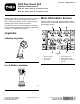
Form No. 3429-304 Rev A 4050 Directional Drill Software Versions A–D Model No. 23898—Serial No. 316000001 and Up Model No. 23899—Serial No. 316000001 and Up Read this information carefully to learn how to operate and maintain your product properly and to avoid injury and product damage. You are responsible for operating the product properly and safely. Visit www.Toro.com for product safety and operation training materials, accessory information, help finding a dealer, or to register your product.
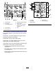
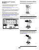
g213150 Figure 5 g287716 Figure 4 1. Pipe functions 6. Engine temperature gauge 2. Fuel gauge 7. Engine droop 3. Limit setting options 8. Thrust force, drill speed (rpm), or rotary torque adjustment 4. Cruise option 9. Horn 1. Pull pipe 4. Thrust force 2. Push pipe 5. Drill speed (rpm) 3. Rotary torque 5. Select pipe row Go to the Mud or Air Hammer Selection Screen (page 15) to switch between mud pressure and air hammer functions.
Cruise Mode and Screen Software version Rev D and up. Cruise mode is identified by this icon: Cruise mode provides hands-free operation for rotary and thrust, set by the operator. Note: Use Cruise mode for pull back only. Using cruise mode in thrust could cause damage. You can only use cruise mode with clockwise functions. Accessing the Cruise Screen Push the cruise button on the joystick (Figure 6) or push button 4 on the home screen to access the cruise screen.
2. Push button 6 or 7 to increase or decrease the value of the selected setting. g290321 Figure 8 The following table describes the function values affected when another function is given priority. The priority is the function with the highest value, not the value selected in the screen. All values are dependent on the available engine horse power.
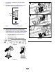
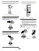
Pulling Pipe in SmartTouch Mode SmartTouch™ Home Screen Start the SmartTouch mode with the cam assembly in the home position (row 4 of the pipe box). SmartTouch mode allows the operator to load and unload pipes from the rod box with less joystick operation to reduce operator fatigue. Use the Carriage Settings Screen (page 14) to turn SmartTouch mode on and off.
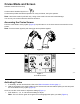
1. Push button 1 to select the pull pipe option (Figure 13). 2. Push buttons 2 and 3 to select the row where you want to place the pipe (Figure 13). g232381 Figure 13 1. Pull pipe 3. 2. Select pipe row Hold the lower right button on the 8-button joystick (Figure 10) or the lower section of the rocker switch (Figure 15) on the 4-button joystick until the following 3 things happen (Figure 16): A. The cam assembly rotates toward the operator station. B. The elevator lowers. C.
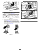
4. Release the rocker switch/button to proceed to the next step in the sequence (Figure 17). 7. Hold the lower right on the 8-button joystick (Figure 10) or the lower section of the rocker switch (Figure 21) of the 4-button joystick until the arms rotate with the pipe back to the home position and the grippers open as the pipe enters the cam assembly pocket (Figure 22). g231713 Figure 17 5. Break the pipe connection; refer to Removing Drill Pipes in the Operator’s Manual. 6.
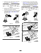
. 11. Release the button/rocker switch to proceed to the next step in the sequence (Figure 23). Hold the lower right button (Figure 10) on the 8-button joystick or the lower section of the rocker switch (Figure 27) of the 4-button joystick until the elevator puts the pipe back in the pipe box and the cam rotates to the home position (Figure 28). g231715 Figure 23 9.
Pushing Pipe in SmartTouch Mode 1. Push button 1 to select push pipe (Figure 32). Start the SmartTouch mode with the cam assembly in the home position (row 4 of the pipe box). 2. Push buttons 2 and 3 to select the row where you want to get the pipe (Figure 32). g236957 Figure 29 1. Go to the previous step 2. Go to the next step g232387 Figure 32 Important: Ensure that you hold the lower section 1.
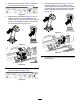
g232382 Figure 35 4. Release the rocker switch to proceed to the next step in the sequence (Figure 36). g231718 Figure 36 5. g232383 Figure 38 Hold the lower right button on the 8-button joystick (Figure 10) or the lower section of the rocker switch (Figure 37) on the 4-button joystick until the cam assembly fully rotates forward to the rack and the elevators lift the remaining pipe into the pipe box (Figure 38).
6. Release the button / rocker switch to proceed to the next step in the sequence (Figure 39). 8. Release the rocker switch to proceed to the next step in the sequence (Figure 42). g231720 g231719 Figure 42 Figure 39 7. 9. Hold the lower right button on the 8-button joystick (Figure 10) or the lower section of the rocker switch (Figure 40) on the 4-button joystick until the loader arms rotate toward the pipe box.
11. Hours Screen Options Hold the lower right on the 8-button joystick (Figure 10) or the lower section of the rocker switch (Figure 46) on the 4-button joystick until the loader arms rotate back and the cam assembly returns to the home position (row 4) (Figure 47). Machine Hours Screen To access this screen, push button 1 on the Hours screen. This screen shows the operating hours of the machine. You cannot change Machine 1 but you can reset Machine 2.
Lubrication and Maintenance Screens To access this screen, push button 3 on the Hours screen. These screens provide the user with the daily maintenance schedules in the increments listed below. To reset the maintenance interval, navigate to the Parameters Options Screen (page 14), push the down arrow to scroll to the maintenance options screen, and enter pin number 12356.
Settings Screen Options Carriage Settings Screen Push button 1 on the Settings screen. Use this screen to change the carriage settings. Use the up and down arrows to rotate between push pipe, pull pipe, and neutral. Joystick Type Left/Right Mode I Mode II 8 or 9-Button Joystick Functions Left Joystick (no action) Rotation Right Joystick Thrust and rotation Thrust Parameters Options Screen Push button 3 on the Settings screen. Push the OK button to turn SmartTouch™ on and off.
Language and Units Options Screen Clock Settings Screen Push button 7 on the Settings screen to set the clock settings options. Push button 5 on the Settings screen to access the language and units Screen. Push the up and down arrows to switch between English units and metric units. Once you are on this screen, push button 7 to rotate between date, time, and 12/24. Use the up and down arrows to adjust the parameters.
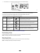
• The lower center icon indicates if the 2-speed selection of the carriage speed has been selected. • The lower right icon indicates the status of the Exit Side Lockout (ESL). If the indicator is black, the carriage and rotary actions are inhibited. Engine I/O Screen To access this screen push button 2 on the I/O screen. This screen displays engine information. g288049 Figure 62 Information (I/O) Screens Joystick I/O Screen Push button 1 on the I/O screen to rotate between the Drill and Setup options.
Joystick Help Screens Air filter icon: the air filter icon is green unless the filter is plugged then the indicator is red. To access these screens push button 4 on the I/O screen. Hydraulic-fluid filter icon: the hydraulic-fluid filter icon is green unless the filter is plugged then the indicator is red. These screens show the function of each joystick button. Engine droop icon: select the allowable engine droop of 80, 90, or 100%.
g290340 Figure 73 g287759 Figure 69 g290341 Figure 74 g287760 Figure 70 8 or 9-Button Joysticks g290342 Figure 75 g290338 Figure 71 g290343 Figure 76 g290339 Figure 72 18
Auxiliary I/O Screen • Shows the seat with an arrow when the operator To access this screen push button 5 on the I/O screen. • All icons change from black to green when you operate the associated functions. seat is unoccupied Shows the seat with a figurine when the operator seat is occupied Exit side lockout icon: changes from black to green when in operation.
The red dot appears in the center of the target and the FNR (forward, neutral, reverse) and Steer voltage shows 2.5 V prior to allowing the drill to move. If the red dot travels outside of the outermost black ring, service or replace the pendant with a new pendant. The indicators to the right and left of the circle show the direction of the track travel. The voltages show a range from 0 to 10.0 V.
Machine Information Screen To access this screen push button 3 on the Errors and Machine Information screen. This screen displays the machine information including the model, serial number, and software version.
Notes:
Notes: