Form No. 3420-334 Rev A Air Hammer Adaptor Kit 2226 Directional Drill Model No. 23920 Model No. 23920E Installation Instructions Loose Parts Use the chart below to verify that all parts have been shipped. Description Bracket Clamp assembly Bolt Nut Reducer Cap Tee fitting Adapter fitting Ball valve Straight fitting Hose Jumper wire harness Hose protector Cable ties 90-degree fitting © 2018—The Toro® Company 8111 Lyndale Avenue South Bloomington, MN 55420 Qty.
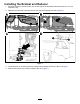
Installing the Bracket and Reducer 1. Move the machine to a level surface, turn off the engine, set the battery disconnect switch to OFF, and remove the key. 2. Raise the front and rear hoods and remove the side panels (Boxes A and B of Figure 1). g248582 Figure 1 3. Locate the area on the frame where the bracket will be installed as shown in Box C of Figure 1. 4. Remove the bolt and nut currently installed. (Box D of Figure 1).
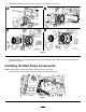
5. Secure the bracket to the frame using 1 bolt and 1 nut (Box A of Figure 2). g248581 Figure 2 6. Loosely install the clamp assemblies onto the bracket (Box B of Figure 2). 7. Place the reducer in the clamps, tighten the clamp assemblies, and install and tighten the cap (Boxes C and D of Figure 2). Installing the Mud Pump Components Note: Install nonstick coated ape on all of the pipe fitting connections. 1. Locate the mud pump components that are currently installed (Figure 3).
2. Disconnect the current mud pump components (Box A of Figure 4). g249326 Figure 4 1. Jumper wire harness 3. Move the components from the side of the tee fitting to the top of the tee fitting (Box B of Figure 4). 4. Install the jumper wire harness to the wire harness previously removed (Box B of Figure 4).
. Move the adapter and valve from the top of the tee fitting to the side of the tee fitting (Box A of Figure 5). g249325 Figure 5 1. Tee fitting 3. Ball valve 2. Adapter fitting 4. Straight fitting 5. Hose 6. Install the tee fitting on the end of the valve and move the previously installed adapter onto the top of the tee fitting (Box B of Figure 5). 7. Move the previously installed hose onto the adapter on the top of the tee fitting (Box C of Figure 5). 8.
Routing the Hose and Installing the Hose Protector 1. Route the hose from the mud pump components behind the hydraulic tank and under the radiator to the bracket assembly (Box A of Figure 6). 2. Install the 90-degree fitting to the end of the reducer and connect the hose (Box B of Figure 6). 3. Install the hose protector onto the hose where the hose touches the radiator and secure it with 3 cable ties (Box C of Figure 6). 4.
Operation Using the Air Hammer Update your software to the most current version; refer to the Software Guide, for the 2226 Directional Drill for more operation information. Turn the air hammer valve to ON to operate the air hammer (Figure 7). Note: Ensure that the mud (normal) drilling valve is turned OFF.