Form No. 3407-349 Rev A Direct Drive Trencher RT600 Traction Unit Model No. 25200—Serial No. 316000001 and Up Model No. 25200E—Serial No. 316000001 and Up Register at www.Toro.com.
WARNING Model No. CALIFORNIA Proposition 65 Warning This product contains a chemical or chemicals known to the State of California to cause cancer, birth defects, or reproductive harm. Serial No. This manual identifies potential hazards and has safety messages identified by the safety-alert symbol (Figure 2), which signals a hazard that may cause serious injury or death if you do not follow the recommended precautions. Introduction Figure 2 1.
Safety WARNING Lightning can cause severe injury or death. Improperly using or maintaining the trencher can result in injury. To reduce the potential for injury, comply with these safety instructions and those in the machine Operator’s Manual. Always pay attention to the safety alert symbol, which means Caution, Warning, or Danger—personal safety instruction. Failure to comply with the instruction may result in personal injury or death.
Safety and Instructional Decals Safety decals and instructions are easily visible to the operator and are located near any area of potential danger. Replace any decal that is damaged or lost. Figure 3 1. Decal 125-6670 2. Decal 125-6671 125–6670 1. Cutting/dismemberment hazard, trencher—keep bystanders away from the trencher; keep away from moving parts; keep all guards and safeties in place. 125-6671 1. Explosion hazard; electric shock hazard—call local utilities before digging.
Preparing the Machine 2. Set the parking brake. Important: Ensure that the lifting equipment has a lifting capacity of at least 405 kg (893 lb). 3. Turn the key to the OFF position. 4. Remove the key. 1. Park the machine on a level surface. 5. Disconnect the battery. Installing the Trencher Attachment Raise the attachment off the floor. Important: Ensure that the lifting equipment has a lifting capacity of at least 405 kg (893 lb).
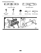
Installing the Auger 4x 4x (5/8 x 2 inches) 4x (5/8 inch) Installing the Restraint-Bar Brackets 1x 1x 8x 8x 8x 8x (M12) (M12 x 4-1/4 inches) (5/8 inch) (5/8 x 2 inches) 6
Installing the Hydraulic Hoses 2x 1x 42 cm (16-1/2 inches) 97 cm (38 inches) 1x 88 cm (34-1/2 inches) 7
Testing the hoses 1. Start the machine; refer to the traction unit Operator’s Manual. 1x 2. Operate the trencher-chain direction control and the attachment control (located on the right side of the operator seat) in both directions several times to bleed the air from the hydraulic motor and the hydraulic lift cylinder. 75 cm (29-1/2 inches) Note: The trencher-chain direction control rotates the hub forward and rearward, and the attachment control raises and lowers the boom-mount fitting.
Installing the Boom Plates 2x 2x Long boom plates Short boom plates 4x 2x 2x 2x 2x (5/8 x 4-1/2 inches) (M12) (M12) Thick bar clamp Thin bar clamp Place thread locking adhesive on 4 bolts (5/8 x 4-1/2 inches) and install them as shown.
Installing the Wear Pad Channel 10x (short boom) 14x (long boom) (M10) Apply thread-locking adhesive to the bolts (M10) and secure the wear-pad channel onto the boom.
Installing the Boom-Roller Assembly 1x 2x 1x 1x 1x 1x (3/4 x 1-1/2 inches) 1. Add grease to the washers and ensure that the washers are flush with the roller surface when installing. 2. Install the boom pin through the boom-roller assembly being careful to center the cone spacers before sliding the pin through. 3. Apply thread-locking adhesive to the bolt and torque to 230 to 258 N∙m (170 to 190 ft-lb). 4.
Installing the Wear Pads and Restraint Bar 1x 1x 5x (short boom) Wear pad (short and long shown) 6x (long boom) (M10) Apply thread-locking adhesive to the bolts (M10) and secure the wear pad onto the boom assembly. Short boom shown Torquing the Hardware Bolts (M10) Bolts (M12) Installing the Digging Chain Refer to Installing the Digging Chain (page 24).
Operation Selecting the Proper Components for the Trencher Using the correct trencher components helps to increase the trenching speed and extending the life of the trencher. Contact an Authorized Toro Service Dealer for more information on parts for your trencher. Figure 21 1. H-plate chain Selecting the Proper Chain Selecting the Proper Digging Teeth It is important to have the correct chain for the job.
The arrangement of digging teeth involves both where and how each tooth is attached to the digging chain. Use the following guidelines when you select the arrangements of teeth: 1 • Install teeth that are the same width and are spaced equally around the chain. • Use fewer teeth on the chain when you are operating the trencher in wet clay or gumbo. • Use more teeth on the chain when you are operating the trencher in sandy loam or rocky ground.
Using the Trencher Positioning the Boom for Trenching For the best trenching performance and the smoothest machine operation, the boom must be in the full down trenching position (Figure 26). Having the boom in this position pulls the machine down for better traction. The ground drive simply pulls the trencher teeth into the face of the trench.
12. Decrease the digging chain speed and look at the tachometer. Note: If the engine speed increases, push the utility-traction lever forward until the engine speed is the same that in step 11. Repeat this step to obtain the best trenching speed. Note: Some hard soil conditions allow you to dig a trench faster by reducing the chain speed. WARNING Operating a trencher attachment without a restraint bar or a crumber could result in server personal injury or death if the chain breaks.
4. Pull the attachment lift lever back to the RAISE position until the boom is in the TRANSPORT position. 5. Move the throttle to the IDLE position, shut off the engine, and remove the key. Operating Tips • Clean the area of trash, branches, and rocks before trenching to prevent damaging the equipment. • Always select the shortest boom, the lightest chain, and the lightest teeth to handle the job.
Maintenance Greasing the Trencher Service Interval: Every 50 hours 1. Clean the grease fittings with a rag. 2. Connect the grease gun to the grease fitting for the bearing of the lower lift cylinder, and apply 3 pumps of grease to the fittings (Figure 28, Figure 29, and Figure 30). 3. Wipe up any excess grease. Figure 30 Servicing the Trencher Digging Chain Checking the Chain Tension Service Interval: After the first 10 hours Figure 28 Before each use or daily 1. Start the engine. 2.
6. Measure the distance between the chain and the bottom of the lower wear strip (Figure 31). • If the gap between the lower wear strip and the chain is 51 to 76 mm (2 to 3 inch), the chain tension is correct (Figure 31). • If the gap is smaller that 51 mm (2 inch), the chain tension too tight; refer to Decreasing the Chain Tension (page 19). • If the gap is larger that 76 mm (3 inch), the chain tension too loose; refer to Increasing the Chain Tension (page 20). 2.
Increasing the Chain Tension 2. Clean the area around the dust cap with a cleaning solvent (Figure 34). WARNING 3. Use a needle-nose pliers to rotate the dust cap counterclockwise and remove the cap from the grease fitting (Figure 34). If you remove the grease fitting from the boom before you release the pressure in the system, personal injury may result. 4. Loosen the bolts that secure the lock bars and the side plates on the left side of the boom (Figure 32).
Torquing the Fasteners on the Chain Drive Sprocket Checking the Trencher Chain Wear Strip and Wear Channel Service Interval: After the first 10 hours Service Interval: Before each use or daily After the first 25 hours 1. Lift the chain at the wear strip at the top of the boom, and check the wear strip for signs of damage or excessive wear (Figure 37).
Replacing the Trencher Chain Wear Strip 4. Remove the wear strip (Figure 39). 5. Clean the threads of the bolts. 1. Loosen the trencher chain; refer to Decreasing the Chain Tension (page 19). 2. Lift the chain at the top of the boom, and install blocks between the chain and the boom (Figure 38). 6. Apply medium-grade (service removable) thread-locking compound to the threads of the bolts. 7. Align the holes of the new wear strip with the holes in the top of the boom (Figure 39).
Replacing the Digging Chain Removing the Digging Chain Preparing to Remove the Digging Chain 1. Start the machine and move the boom to the full up position. 2. Rotate the digging chain until the master pin is positioned at the top of the idler wheel of the boom (Figure 42). 3. Turn the machine off, and remove the key. 4. Remove the bleed plug from the chain tensioner of the boom; refer to Checking the Chain Tension (page 18).
Aligning the Digging Chain 5. When the digging chain has cleared the drive sprocket, move the trencher drive control to the NEUTRAL position, turn the machine off, and remove the key (Figure 43). This procedure requires 2 people to align the digging chain to the machine. 1. Route the ends of the lifting strap forward of the sprocket hub, on either side of the drive sprocket, and up past the dirt deflector (Figure 45). 6.
Storage 1. Before storing the machine, brush off the dirt from the attachment. 2. Check the condition of the digging chain. Adjust and lubricate the chain. Replace any worn or damaged parts. 3. Check and tighten all bolts, nuts, and screws. Repair or replace any part that is damaged or worn. 4. Ensure that all hydraulic couplers are connected together to prevent contaminating the hydraulic system. 5. Paint all scratched or bare metal surfaces with paint available from an Authorized Service Dealer. 6.
Troubleshooting Problem The chain does not turn. Possible Cause 1. A hydraulic fitting is not completely connected. 1. Check and tighten all fittings. 2. A hydraulic fitting is damaged. 3. There is an obstruction in a hydraulic hose. 4. An auxiliary valve on the machine is not opening. 5. The boom-end bearing has failed. 6. The digging chain is too tight. 7. There is sand buildup in the tooth root of the drive sprocket. 2. Replace the damaged fitting. 3. Find and remove the obstruction. 8.
Notes:
Underground Equipment The Toro Warranty A Limited Warranty Conditions and Products Covered The Toro Company and its affiliate, Toro Warranty Company, pursuant to an agreement between them, jointly warrant your Toro Underground Equipment (“Product”) to be free from defects in materials or workmanship. Where a warrantable condition exists, we will repair the Product at no cost to you including diagnostics, labor, and parts.