
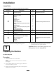
Installation Instructions


InstallingtheHydraulicHosesforthe
Direct-DriveTrencher
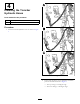
UseFigure11forthettingposition.
•F16ttingata108-degreeangle
•F12ttingata90-degreeangle
Figure11
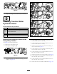
1.Installthe50-inchhosewiththeF12ttingasshown
inBoxAofFigure12.
Figure12
2.Torquethettingonthehydraulicattachmentpanelto
149to184N∙m(110to136ft-lb).
3.Torquethettingonthetrencherhydraulicmotorto
89to111N∙m(66to82ft-lb).
4.Installthereduceradaptertothe50-inchhosewiththe
F16ttingasshowninBoxBofFigure12.
5.Torquethettingto89to110N∙m(66to82ft-lb).
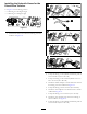
6.Installtheotheradaptertothe46-inchhoseasshown
inBoxBofFigure12.
7.Torquethettingto45to56N∙m(33to41ft-lb).
8.Installtheother50-inchhosewiththeF16ttingas
showninBoxCofFigure12.
9.Torquethettingonthehydraulicattachmentpanelto
149to184N∙m(110to136ft-lb).
9