Form No. 3373-917 Rev B Pro Sneak 360 Vibratory Plow Model No. 25400—Serial No. 313000001 and Up g019008 Register at www.Toro.com.
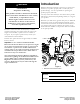
Introduction WARNING Read this information carefully to learn how to operate and maintain your product properly and to avoid injury and product damage. You are responsible for operating the product properly and safely. CALIFORNIA Proposition 65 Warning This product contains a chemical or chemicals known to the State of California to cause cancer, birth defects, or reproductive harm. You may contact Toro directly at www.Toro.
Servicing the Battery...............................................28 Drive System Maintenance .........................................30 Checking the Tires and Lug Nuts .............................30 Changing the Transmission Oil.................................30 Changing the Axle Oil.............................................30 Cooling System Maintenance ......................................31 Servicing the Cooling System ...................................31 Belt Maintenance ......................
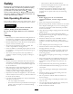
Safety Improper use or maintenance by the operator or owner can result in injury. To reduce the potential for injury, comply with these safety instructions and always pay attention to the safety alert symbol , which means: Caution, Warning, or Danger—personal safety instruction. Failure to comply with the instruction may result in personal injury or death. • Operation • Before digging, have the area marked for Safe Operating Practices This product is capable of amputating hands and feet.
• Do not operate near drop-offs, ditches, or embankments. • Ensure that the area is clear of other people before • • • • • • • • • • The machine could suddenly turn over if a wheel goes over the edge of a cliff or ditch, or if an edge caves in. operating the machine. Stop the machine if anyone enters the area. Never leave a running machine unattended. Always stop the engine, set the parking brake, and remove the key before leaving. Never jerk the controls; use a steady motion.
– Never store the machine or fuel container inside where there is an open flame, such as near a water heater or furnace. – Never fill a container while it is inside a vehicle, trunk, pick-up bed, or any surface other than the ground. – Keep container nozzle in contact with the tank during filling. • Stop and inspect the equipment if you strike an object. Make any necessary repairs before restarting. • Use only genuine Toro replacement parts to ensure that original standards are maintained.
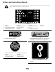
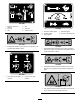
Safety and Instructional Decals Safety decals and instructions are easily visible to the operator and are located near any area of potential danger. Replace any decal that is damaged or lost. 106-9290 1. Inputs 5. In seat 2. Not active 6. Power Take-off (PTO) 9. Outputs 10. Power Take Off (PTO) 3. High temperature shutdown 7. Parking brake Off 11. Start 4. High temperature warning 12. Energize to Run (ETR) 8. Neutral 114-9600 13. Start 14. Power 120-0627 1. Read the Operator's Manual. 1.
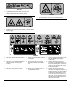
125–6670 1. Cutting/dismemberment hazard, trencher—keep bystanders away from the trencher; keep away from moving parts; keep all guards and safeties in place. 125–6672 1. Crushing hazard—stay away from articulated joints. 125-6671 1. Explosion hazard; electric shock hazard—call local utilities before digging. 125–6673 1. Warning—read the Operator’s Manual. 4. Warning—keep bystanders away from the machine. 7. Explosion hazard; shock hazard—call the local utilities before digging underground. 2.
125–6677 1. Engine—stop 3. Engine—start 2. Engine—run 125–6674 1. Disengage the parking brake. 2. Engage the parking brake. 125–6675 1. Raise/lower the plow. 125–6678 2. Raise/lower the trencher. 1. Turn the trencher clockwise. 2. Stop the trencher. 3. Turn the trencher counterclockwise. 125–6679 1. For information on preheating the engine, read the Operator’s Manual. 125–6676 1. Raise/lower the trencher. 2. Raise/lower the plow.
125–6680 1. Read the Operator’s Manual. 2. Turn left 4. Fast 3. Slow 6. Traction control 125-6683 5. Turn right 1. Pull out for fastest speed 4. Decrease speed 2. Increase speed 5. Push in for slowest speed 3. Engine speed 125–6681 125–6684 1. Entanglement hazard—keep away from moving parts; keep all guards and safeties in place. 1. Cutting/dismemberment hazard, plow—keep bystanders away from the plow; stay away from moving parts; keep all guards and safeties in place. 125–6686 1.
125–6688 1. Explosion hazard—Read the Operator’s Manual; Do not use starting fluid. 125–8487 1. Crushing hazard, tire—read the Operator’s Manual; the extension step must be attached when the tires are in wide or doubled configuration. 125–6694 1. Tie down location 125–8491 1. Crushing hazard, warning—keep away from articulated joints; replace missing safety shields. 125–8483 1. Hydraulic fluid; read the Operator’s Manual. 125–8488 1. Turn clockwise 2. Stop rotation 11 3.
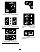
Product Overview 1 2 3 4 5 6 8 7 g019007 9 Figure 3 1. Control panel 4. Engine-oil filter 7. Front tie-down bar 2. Hood latch 5. Engine-oil dipstick 8. Air cleaner 3. Hood handle 6. Fuel filter 9. Rear tie-down bar Controls You can rotate the knob to make small adjustments to the engine speed. Rotate the knob counterclockwise to increase engine speed and clockwise to decrease engine speed. Become familiar with all the controls (Figure 4) before you start the engine and operate the machine.
Move the lever to the neutral position to stop the machine. Key Switch From the neutral position, push the lever slightly for forward ground travel. Push the lever farther to increase the forward ground speed. Pull the lever slightly to decrease the forward ground speed. The key switch, used to start and stop the engine, has four positions: on, off, and start. To start the engine, rotate the key to the start position. Release the key when engine starts and it will move automatically to the on position.
Neutral Indicator Light Operation This light illuminates when all control levers are in the neutral position. Note: Determine the left and right sides of the machine from the normal operating position. Specifications Important: Before operating, check the fuel and oil level, and remove debris from the machine. Also, ensure that the area is clear of people and debris. You should also know and have marked the locations of all utility lines.
Filling the Fuel Tank 1. Lift the operator seat to access the fuel tank. 2. Remove the fuel tank cap (Figure 7). DANGER 1 In certain conditions, fuel is extremely flammable and highly explosive. A fire or explosion from fuel can burn you and others and can damage property. • Fill the fuel tank outdoors, in an open area, when the engine is cold. Wipe up any fuel that spills. • Never fill the fuel tank inside an enclosed trailer.
Note: The level should be even with the bottom of the fill plug 8. If the oil level is low (below the bottom hole), clean around the oil filler cap and remove the cap (Figure 9). 5. If the oil level is below the bottom of the fill plug hole, add oil to raise the level up to the bottom of the fill plug hole. 6. Install the fill plug. Checking the Axle Oil Levels Service Interval: Every 100 hours 1 1. Park the machine on a level surface, lower any attachments, and stop the engine. g022228 Figure 9 2.
Checking and Adding the Engine Coolant 2. Stop the engine, remove the key, and allow the engine to cool. 3. Open the hood. Service Interval: Before each use or daily 4. Clean the area around the filler neck of the hydraulic tank (Figure 12). Clean any debris off of the screen, oil cooler, and front of the radiator daily and more frequently when operating conditions are extremely dusty or sandy. The cooling system is filled with a 50/50 solution of water and permanent ethylene glycol antifreeze.
1 1. Ensure that the fuel tank is at least half full. 2. Open the hood. 3. Open the air bleed screw on the fuel injection pump (Figure 15). g018959 Figure 14 1. Coolant expansion tank fill cap If the coolant level is low, complete the following procedure: 1. Remove the coolant expansion tank fill cap (Figure 14). 2. Add coolant into the expansion tank until it reaches the upper mark on the expansion tank. Figure 15 3. Install the expansion tank cap. 1.
Starting and Stopping the Engine Operating the Vibratory Plow Plowing 1. Start the engine. 2. When the engine is warm, pull the throttle out to full throttle (Figure 16). Starting the Engine 1. Adjust the seat and fasten the seat belt. 2. Ensure that all of the control levers are in the Neutral or Stop position. 1 2 3 3. Move the throttle lever midway between the Slow and Fast positions. 4. Turn the ignition key to the Start position. When the engines starts, release the key.
9. Use the direction or creep control levers to steer the machine to the left or right. Important: Do not reverse the machine with the plow blade in the ground. Important: Slowly lift the plow blade out of the ground as the machine moves forward. Note: Decrease the machine speed if the tires slip or the blade raises out of the ground during plow operation. 1 2 10. Reduce the speed of the machine and press the PTO switch to stop the plow vibration before raising the blade out of the ground.
7. Stop the engine and remove the key. 8. Put blocks at the front and rear of each tire of the machine. 9. Fasten the front of the machine to the trailer using chains and a binder. Use the front tie down hole (Figure 21) to secure the machine. g022223 Figure 19 4. Install the wheels on the opposite side of the machine from which each was removed. 1 g018921 5. Remove the front wheels and install them on the opposite side of the machine from which each was removed. Figure 21 1.
Unloading the Machine 1. Put a block at the front and rear of the machine and trailer wheels. 2. Remove the chains, then remove the blocks from the machine. 3. Ensure that the attachments are in the transport position. 4. Start the engine and release the parking brake. Refer to Starting the Engine (page 19). 5. Slowly move the machine off of the trailer. Using Attachments Important: Use only Toro-approved attachments. Attachments can change the stability and the operating characteristics of the machine.
Maintenance Note: Determine the left and right sides of the machine from the normal operating position. Recommended Maintenance Schedule(s) Maintenance Service Interval Maintenance Procedure After the first 25 hours • Replace the hydraulic filter. After the first 50 hours • Change the engine oil and filter. After the first 250 hours • Change the hydraulic fluid. Before each use or daily • • • • • • • • • • • Check the engine oil level. Check the hydraulic fluid level. Check the cooling system.
CAUTION If you leave the key in the ignition switch, someone could accidently start the engine and seriously injure you or other bystanders. Remove the key from the ignition before you do any maintenance. Premaintenance Procedures Lubrication Greasing the Machine Before opening any of the covers, stop the engine and remove the key. Allow the engine to cool before opening any covers. Service Interval: Before each use or daily (Grease immediately after every washing).
Engine Maintenance Servicing the Air Cleaner Service Interval: Before each use or daily—Check the air filter service indicator light (more frequently if conditions are dusty or sandy). Every 25 hours—Remove air cleaner cover, clean out debris, and check the air filter service indicator light (more frequently if conditions are dusty or sandy). Every 1,000 hours/Yearly (whichever comes first)—Replace the safety air filter (more frequently if conditions are dusty or sandy).
Replacing the Filters Changing the Oil 1. Gently slide the primary filter out of the air cleaner body (Figure 28). Avoid knocking the filter into the side of the body. 1. Start the engine and let it run for 5 minutes. This warms the oil so it drains better. 2. Park the machine so that the drain side is slightly lower than the opposite side to ensure that the oil drains completely. 2.
Changing the Oil Filter Fuel System Maintenance 1. Drain the oil from the engine; refer to Changing the Oil (page 26). 2. Place a shallow pan or rag under the filter to catch the oil. DANGER Under certain conditions, diesel fuel and fuel vapors are highly flammable and explosive. A fire or explosion from fuel can burn you and others and can cause property damage. 3. Remove the old filter (Figure 31) and wipe the surface of the gasket seal on the filter head.
Electrical System Maintenance Servicing the Battery 1 Service Interval: Every 100 hours—Check the battery electrolyte level (replacement battery only). Every 250 hours—Check the battery cable connections. WARNING g018962 CALIFORNIA Proposition 65 Warning Battery posts, terminals, and related accessories contain lead and lead compounds, chemicals known to the State of California to cause cancer and reproductive harm. Wash hands after handling. Figure 32 1. Fuel filter 2.
5. Wait 5 to 10 minutes after filling the battery cells. 4. Look at the side of the battery. Note: The electrolyte must be up to the Upper line (Figure 34). Do not allow the electrolyte to fall below the Lower line (Figure 34). Note: Add distilled water, if necessary, until the electrolyte level is up to the Upper line (Figure 34) on the battery case. 6. Install the battery filler caps. Charging the Battery 2 WARNING 3 Charging the battery produces gasses that can explode.
Drive System Maintenance 1 Checking the Tires and Lug Nuts Service Interval: Before each use or daily—Check the tire pressure. Before each use or daily—Check the lug nuts. • Do not exceed the rated tire pressure. To ensure long tire life and safe handling, check tire pressure daily, refer to Checking the Tire Pressure (page 18). 2 • Proper Care-Inspect tires for cuts, slashes, or bulges. g022229 Tires with defects need to be replaced or repaired for proper handling and safety.
Cooling System Maintenance 7. Fill with differential oil until the oil is level with the bottom of the fill plug hole. 8. Install the fill plug. 9. Repeat the procedure for the other differential. Servicing the Cooling System Service Interval: Before each use or daily—Clean the radiator. Every 100 hours—Check the cooling system hoses. Yearly—Change the engine coolant (Authorized Service Dealer only). DANGER If the engine has been running, the pressurized, hot coolant can escape and cause severe burns.
Belt Maintenance Controls System Maintenance Checking the Alternator Drive Belt Tension The factory adjusts the controls before shipping the machine However, after many hours of use, you may need to adjust the controls. Service Interval: Every 1,000 hours Important: To adjust the controls properly, complete each procedure in the order listed. 1. Push the drive belt with your thumb in the area shown to check the tension (Figure 39). Note: The deflection should be between 7 to 9 mm (0.28 to 0.
Hydraulic System Maintenance 3. Tighten the set-screw catch until the catch bottoms out against the steering control pivot, then loosen the screw 1/2 to 3/4 turn. 4. Install the access panel. Replacing the Hydraulic Filter Service Interval: After the first 25 hours Every 250 hours Important: Do not substitute an automotive oil filter or severe hydraulic system damage may result. 1. Position the machine on a level surface. 2. Lower any attachments, stop the engine, and remove the key. 3.
5. Pinch the hose shown in Figure 42and remove the clamp on the other end attached to the tee adapter. WARNING Hydraulic fluid escaping under pressure can penetrate skin and cause injury. Fluid injected into the skin must be surgically removed within a few hours by a doctor familiar with this form of injury or gangrene may result. • Keep your body and hands away from pin hole leaks or nozzles that eject high pressure hydraulic fluid. • Use cardboard or paper to find hydraulic leaks, never use your hands.
12. Install the hose shown in Figure 42. Checking the Hydraulic Lines 13. Fill the hydraulic tank with approximately 25.8 L (6.8 US gallons) of Toro premium all season hydraulic fluid ISO VG 46; refer to Checking the Hydraulic Fluid Level (page 16). Service Interval: Every 100 hours—Check the hydraulic lines for leaks, loose fittings, kinked lines, loose mounting supports, wear, weather, and chemical deterioration. (Make necessary repairs before operating.
Cleaning Storage 1. Lower any attachments, stop the engine, and remove the key. Removing Debris from the Machine 2. Remove dirt and grime from the entire machine. Important: You can wash the machine with mild detergent and water. Do not pressure wash the machine. Avoid excessive use of water, especially near the control panel, engine, hydraulic pumps, and motors.
Troubleshooting Problem The starter does not crank. Possible Cause 1. The controls are not in the neutral position. 1. Move all of the controls to the neutral position. 2. The electrical connections are corroded or loose. 3. A fuse is blown or loose. 4. The battery is discharged. 5. The relay or switch is damaged. 2. Check the electrical connections for good contact. 3. Correct or replace the fuse. 4. Charge the battery or replace it. 5. Contact your Authorized Service Dealer. 6.
Problem The engine runs, but knocks or misses. Possible Cause 1. There is dirt, water, stale fuel, or incorrect fuel is in the fuel system. 1. Drain and flush the fuel system; add fresh fuel. 2. The engine is overheating. 2. Refer to troubleshooting item The engine overheats. 3. Bleed nozzles and check for air leaks at the fuel hose connections and fittings between the fuel tank and engine. 4. Contact your Authorized Service Dealer. 5. Contact your Authorized Service Dealer. 6.
Problem Excessive white smoke from exhaust. Possible Cause 1. The key was turned to the start position before the glow plug light turned off. 1. Turn the key to the run position and allow the glow plug light to turn off before starting the engine. 2. The engine temperature is low. 3. The glow plugs are inoperative. 4. The injection pump timing is incorrect. 2. Check the thermostat. 3. Check the fuse, glow plugs and wiring. 4. Contact your Authorized Service Dealer. 5.
Astec Brand Product Sold after November 1, 2012 The Toro Underground Warranty A Limited Warranty Conditions and Products Covered The Toro Company and its affiliate, Toro Warranty Company, pursuant to an agreement between them, jointly warrant your Toro Underground product (“Product”) to be free from defects in materials or workmanship. Where a warrantable condition exists, we will repair the Product at no cost to you including diagnostics, labor, and parts.